Is there a hardware SPI overlay I can use?
Using an OLED 128x128 RGB with BelaMini

On BelaMini you can use config-pin out of the box, which is easier than creating an overlay*.
If I get it right, in order to enable the pins with the functionalities advertised here, you should do:
config-pin P2.25 spi
config-pin P2.27 spi
config-pin P2.29 spi_sclk
config-pin P2.31 spi_cs(use, e.g.: config-pin -l P2.29 to see the available modes)
Note that by doing this you will lose access to Bela digital pins 10 and 11 (see here) **.
* it appears that there is no overlay for simply enabling the SPI1 port on the PB, although this MAY work, but some pins may have to change, because it's for the BBB.
** if you really cannot afford losing those two pins, you should explore whether the same signals are available on other pins that are not used by Bela
That seems helpful, but I'm having some confusion about how this works. Hence more questions 
Using SPI1 could be a problem. I'm not using D10 or D11, so that's ok as long as supercolider doesn't cause interference when it starts. I was under the impression that the Digital ports couldn't be used in this scenario, is that the case?
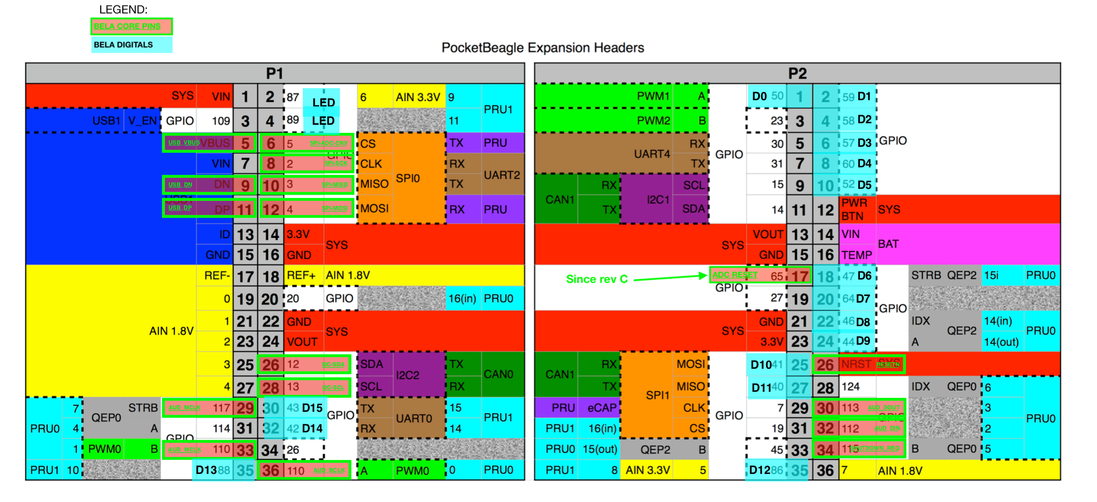
I am using GPIO7 (P2_29) and GPIO19 (P2_31). Maybe I can find other GPIOs but I've used a bunch already and I'm not confident I can find more. I'm still not confident of the best way to find all of them. Related to that, when I try to reference the PocketBeagle Expansion Headers diagram, I'm not sure I understand how to read it. There are some boxes that have dotted lines, other than have bright green, and then other's that look like they are highlighted vs being colored in. Is there a legend or description that helps clarify the diagram?
I think I understand that SPI0 is in a software mode. But I don't know what that means now. I see that config-pin P1_6 spi_cs returns "pinmux file not found! Pin has no cape". I don't know what this message means, I thought cape was the physical header that sits on top, so how can it not have a cape? And if I can configure SPI1 with config-pin and now overlay, then why can't I use config-Pin for SPI0?
I can look into the overlay for SPI0. I have no experience with these, but that usually doesn't stop me. My guess is that you can turn the .dts file into a binary .dtbo file. My only hesitation is bricking the board. If I have a backup of the uEnv.txt file, am I safe?
Each pin on the PocketBeagle (or the BeagleBone) can be assigned to have one of several functions, using the pinmuxer (pin-multiplexer), I wrote a bit about pinmuxer here.
PaulELong Related to that, when I try to reference the PocketBeagle Expansion Headers diagram, I'm not sure I understand how to read it. There are some boxes that have dotted lines, other than have bright green, and then other's that look like they are highlighted vs being colored in. Is there a legend or description that helps clarify the diagram?
If you are looking at this, then the solid colors are as they were found on Beagleboard's original diagram (a more modern version of which, including a legend, is in figure 42 here). They represent some of the function that the pin can assume. On top of that, I overlaid in semi-transparent blue the Bela digital pins, and in a green square with a brief description, the pins used by the Bela core.
The pinmuxer can only be programmed from kernel space in order to change the function of a pin. There are two ways of doing so: device tree overlays, and config-pin, which is the easiest on the PocketBeagle. More details on that are here. The overlays were introduced by Beagleboard on the BeagleBone Black, and in principle each overlay is the digital equivalent of a given cape: you can physically attach a cape, but in order to enable its functionalities you have to load the overlay that tells the computer what is connected where. On the BBB you can load capes while the computer is running, using the capemgr (cape manager), however this is now being phased out, and on the PB you can only load device tree overlays at boot. On the PB, the only way to change pins while the computer is running is to use config-pin.
Now, config-pin can only control those pins that in the device tree have been assigned to a specific "virtual cape". The Bela device tree overlay disables the virtual cape for those pins that are critical to Bela's functioning, which is why for some pins you get pinmux file not found! Pin has no cape (SPI0 is used by Bela, and you should not use it for anything else).
The overlays also take care of doing something more than setting the pinmuxer: they ask the kernel to load a suitable device driver. In the case of config-pin, the driver is already loaded in the device tree.
Now, what are these commands actually doing?
config-pin P2.25 spi
config-pin P2.27 spi
config-pin P2.29 spi_sclk
config-pin P2.31 spi_cs
They are telling the PB to enable the specified pinmuxer configuration for the specified pin. After running config-pin P2.25 spi, for instance, P2.25 will cease been a GPIO (which is the setting it needs to have in order to work as a Bela digital), and is instead connected to the SPI1.MOSI (master-out-slave-input) signal. At this point, toggling GPIO41, the signal that is normally assigned with it, will have no effect, but the pin can be used for SPI communication. This will not be a "soft" SPI, but a "hardware" SPI *.
PaulELong , so that's ok as long as supercolider doesn't cause interference when it starts.
If I have been any clear until now, Supercollider CANNOT cause any interference, because Sc (through Bela) controls the GPIO pins, but these pins are no longer connected to the GPIO signals now, so anything that happens to the GPIOs will not be reflected there).
PaulELong Is there a hardware SPI overlay I can use?
You shouldn't need it. The config-pin settings above should do instead of the overlay. Note that I think that /dev/spidev1 corresponds to the pins labelled SPI0 and /dev/spidev2.1 is the device actually available on P9.25-27-29-31.
Hope this helps.
* a SPI peripheral has several pins which provide functions such as SCK(serial clock)/MISO(master in slave out)/MOSI(master out slave in)/CS(chip select).
Soft SPI: the operating system toggles each pin individually and controls the timing. This requires a lot of CPU time and the speed is therefore very limited (< 100kHz).
Hardware SPI: the operating system configures the peripheral, and then for each transmission it writes one or more "words" in one go. The SPI peripheral (i.e.: some dedicated circuit on the chip) generates the necessary serial signal. This requires very little CPU time (because the data transmission itself is performed by the dedicated circuitry) and the speed can be much higher (up to 24 or 48MHz on the PB/BBB)
- Edited
The info in the chart is clearer now that you've explained it. Since I didn't have the original to reference, it was hard to tell what you added, and what was there originally.
Currently SuperCollider is using D6-D9 for physical switches. So I think I understand that if I use Config-pin to change the functionality as you show above, SuperCollider can't use D10 and D11, but the other's should continue to work fine?
You mentioned this SPI library above. And you said that with SPI0 it wouldn't be fast because it was using soft SPI. But the same library should be fast with SPI1 because it's hardware based?
Two YES's and I'm on my way
PaulELong Currently SuperCollider is using D6-D9 for physical switches. So I think I understand that if I use Config-pin to change the functionality as you show above, SuperCollider can't use D10 and D11, but the other's should continue to work fine?
correct
PaulELong You mentioned this SPI library above. And you said that with SPI0 it wouldn't be fast because it was using soft SPI. But the same library should be fast with SPI1 because it's hardware based?
Right, I see what happened there. I now looked at the source dts of the .dtbo you were trying to load. That would not work on the PB, because it doesn't disable the virtual cape needed by config-pin. If you look at your dmesg when booting with that, you will find an error that tells you it didn't work:
[ 10.604135] pinctrl-single 44e10800.pinmux: pin PIN10 already requested by ocp:P1_34_pinmux; cannot claim for spi_gpio
[ 10.816733] pinctrl-single 44e10800.pinmux: pin-10 (spi_gpio) status -22
[ 10.892373] pinctrl-single 44e10800.pinmux: could not request pin 10 (PIN10) from group pinmux_bb_spi_gpio_pins on device pinctrl-single
[ 11.067361] spi_gpio spi_gpio: Error applying setting, reverse things back
[ 11.126998] spi_gpio: probe of spi_gpio failed with error -22even if it did manage to load correctly, it would still not work, because only two of the pins it requires are available on the PB. Earlier, I had assumed that you were actually using the SPI device that would come up when loading that overlay. But now that I read the docs, that one would actually be /dev/spidev32766.0.
PaulELong And you said that with SPI0 it wouldn't be fast because it was using soft SPI. But the same library should be fast with SPI1 because it's hardware based?
So what I meant here was: the SPI port that you create by using the CTAG overlay would be soft and slow. /dev/spidev1* and /dev/spidev2* are hardware and (potentially) fast.
PaulELong I have the USE_BELA configure SPI via "DEV_HARDWARE_SPI_begin((char *)"/dev/spidev1.0");" line (in OLDEV_Driver.c. So I think SPI port is in use and working, but very slow because the code uses generic access by reading from the /dev/spidev1.0 port. I'm thinking your library will be direct and fast, so that's what I'm investigating next. Let me know if I'm misunderstanding anything.
Hmmm this would mean that you used Bela's own SPI port, which raises two questions:
- if this was running alongside the Bela program with analogs enabled, then the two should have interfered, because that is the port that Bela uses for the analogs
- why was it slow? It doesn't look like you are calling
DEV_HARDWARE_SPI_beginSet(), where the speed is set, so you'd be using the default value of 2MHz.
When I ran the demo app with it wired to SPI0, I wasn't running with a bela app. Perhaps that's why it worked without interference. You say that the overlay I selected shouldn't have done anything, though the demo app works in that configuration. So I'm guessing it would have worked without the overlay, but since this isn't going to work due to potential interference with a Bela app anyways, I switched my wiring to user SPI1.
I modified the demo code to use /dev/spidev2.1 and used new GPIO pins for reset and DC for the OLED. I added constants for the OLED pins in DEV_Config.h (which is committed to my repo). I was using P2_31 and P2_33 for reset and DC, but now I changed to P1_30 and P1_32. I changed the code to specify a speed, DEV_HARDWARE_SPI_beginSet((char *)"/dev/spidev2.1", SPI_MODE0, 24000000);. I tried spidev2 and spidev1 as well, but these didn't work at all.
The demo worked in this new configuration, but it is still slow. Changing the speed of the init code from 2000000 (or 2M), to 8M to 16M to 24M didn't change the speed of the demo. One demo draws every pixel on the screen with bands of colors. It takes about 1-2 secs to complete. The OLED is 128x128x16, so my expectation was that it should easily send 262,144 bits in under a second. In fact, even at 2M, it should be faster than 1 sec to draw the enter screen correct?
Do I have something configured incorrectly for Hardware SPI to work?
An obvious issue would be if you had
#define INTERFACE_4WIRE_SPI 0, as that would revert to a "soft SPI" ( you can see it in Write_Data() in obj/OLED_Driver.c), but I see it in the code it is actually:
#define INTERFACE_4WIRE_SPI 0PaulELong , it should be faster than 1 sec to draw the enter screen correct?
YES
PaulELong I tried spidev2 and spidev1 as well, but these didn't work at all.
? what are these?
so which one DID work (though slow) and which ones did NOT work?
With my original wiring to SPI0, I used /dev/spidev1.0 in the code. This worked fine, though slow.
Then I switch to SPI1, and found that /dev/spidev2.1 worked, though slow. I also tried /dev/spi1.0 and /dev/spidev2.0, and both of those failed to display anything. I tried these other ports because I was uncertain how these map to the physical pins. At first I assumed SPI0 = /dev/SPI1. and SPI1 = /dev/SPI2., but no I've found https://github.com/beagleboard/pocketbeagle/wiki/FAQ#Why_isnt_SPI1_working_for_me. I assume this is the same for belamini, though since I believe the OS is different between the two, I never know when the Pocketbeagle information can be trusted.
I saw on some other Linux versions that you can use some kernel configuration to hardware enable SPI. Is that required here?
I believe I've determined the bottleneck. The demo sends data one byte at a time. I created a buffer for the entire screen, and I can already tell it is much faster. I will write some tests to see how fluid it is and maybe measure the frame rate. The code will need a rewrite, or a better library so updates are done in batches.
The SPI buffer size is limited to 4096. I saw I can change this on a different Linux version by editing /boot/cmdline.txt. I didn't see this file, so I'm wondering do you know the equivalent type of setting for Bela/Xenomai?
PaulELong t first I assumed SPI0 = /dev/SPI1. and SPI1 = /dev/SPI2.,
that is correct, according to the reference you found, and it would be the same on BElaMini.
PaulELong I saw on some other Linux versions that you can use some kernel configuration to hardware enable SPI.
No. that is already enabled.
So, I ran your code (this commit: 05571b259976a493fb7a9392ea028d6c52a7cbc0) on the board and hooked up pins P2.25, P2.27, P2.29, P2.31 to scope.
What I see is that:
- each transmission transmits 8bits
- the bit clock rate is effectively 24MHz
- between the CS line going down and the start of the transmission there are about 3-4us
- between the end of the transmission and the CS line going up there are about 1.4us
- in between transmissions, the CS line stays high for about 37us
(the above are typical values, but things get worse in some cases, e.g.: when the thread is preempted)
So, ultimately, the bottleneck is not in the clock speed of the transmission itself, but mostly the dead time before and after the transmission.
There are ways this could be improved by packing multiple bytes in a single transmission, or in a single ioctl() (see e.g. the DEV_HARDWARE_SPI_Transfer() function in dev_hardware_SPI.c), but how this can be done depends on the characteristics of the device: can it use larger words (e.g.: 32bit)? can it receive several words within a single chip-select cycle?
See more details on what parameters to pass to the ioctl here.
I am a bit surprised by the large overhead that comes with each transfer, but I cannot see where the device could be configured to perform better, and in fact I tried the library I linked above and it performs exactly the same : in a tight loop it takes about 40us per each 8-bit transaction.
- Edited
I believe I'm now getting 54 frames per second, sending 4096 size ioctl calls using 24MHz. If I set to 2Mhz, the rate falls to 5 frames/sec. I think this should more than good enough to do what I want, so I'm going to move forward with this configuration. I haven't been able to find a graphics library that uses a buffer so my thinking is to convert this demo code into a library so I can write to a buffer first, then update the screen as needed.
Appreciate all the help!
BTW, I checked in new code with the changes I made using a buffer, and sending the entire buffer at a time.
I have run into a problem. Supercollider causes my OLED SPI demo to stop. I can reproduce this problem by running the LED blink sc example. If I set s.options.numDigitalChannels = 1, then my demo doesn't display anything, though it continues to run. If the demo is running at the time you start the sc eample, the display goes blank (turned off or all black). If I use s.options.numDigitalChannels = 0, the demo runs fine. I see a small glitch in the animation when it starts, but it still completes.
Why supercollider interfering with my OLED SPI example?
Does the same happen when running a C++ Bela project?
Yes, the C++ passthrough example, if running, prevents the demo from showing anything on the display. And if I turn disable digital from project settings, the demo app works fine.
Ok, can you please detail all the pins that are connected to the display?
Vcc => P1_14 (shared)
Gnd => shared
DIN => P2_25
CLK => P2_29
CS => P2_31
DC => P1_30
RST => P1_32
P1_30 and P1_32 are Bela D15 and D14 pins https://raw.githubusercontent.com/wiki/BelaPlatform/Bela/Images/BelaMiniPinout.png , so the Bela code takes over them. Can you select some other GPIO for those tasks?
I guess i thought that since P25 and P27 are also Digital(10/11), and I'm using those for SPI1, that using other digital pins should work. But now re-reading (https://forum.bela.io/d/978-using-an-oled-128x128-rgb-with-belamini/10), I think you are saying when pings are assigned as GPIOs, bela will take them, but since I assigned to SPI bela won't. So I see how P1_30 and P_32 aren't available to me.
So as far as finding new GPIOs, I think I've used them all up. I'm currently using 6 for the LCD, 1 for the bluetooth enable, and UART4 takes away 2.
UART4 RX - P2_5 GPIO_30
UART4 TX - P2_7 GPIO_31
LCD E - P2_03, GPIO 23
LCD RS - P2_19, GPIO 27
LCD 4 - P1_31, GPIO_131
LCD_5 - P2_17, GPIO_65
LCD_6 - P1_34, GPIO 114
LCD_7, P1_20, GPIO 20
BT_E, P2_28, GPIO 116 (BTW, the diagram says it's 124, but 116 works for me, maybe it's wrong)
In the end, I won't have both an LCD and OLED screen, but during development it's helpful to have both. I think P1_3, P2_9, P2_11, p2_33 should be available based on the diagram, but config-pin gives me errors. Maybe that means I have to do some overlay voo-doo, but am I missing any available GPIOs?