• Hardware
  • Using an OLED 128x128 RGB with BelaMini

PaulELong t first I assumed SPI0 = /dev/SPI1. and SPI1 = /dev/SPI2.,

that is correct, according to the reference you found, and it would be the same on BElaMini.

PaulELong I saw on some other Linux versions that you can use some kernel configuration to hardware enable SPI.

No. that is already enabled.

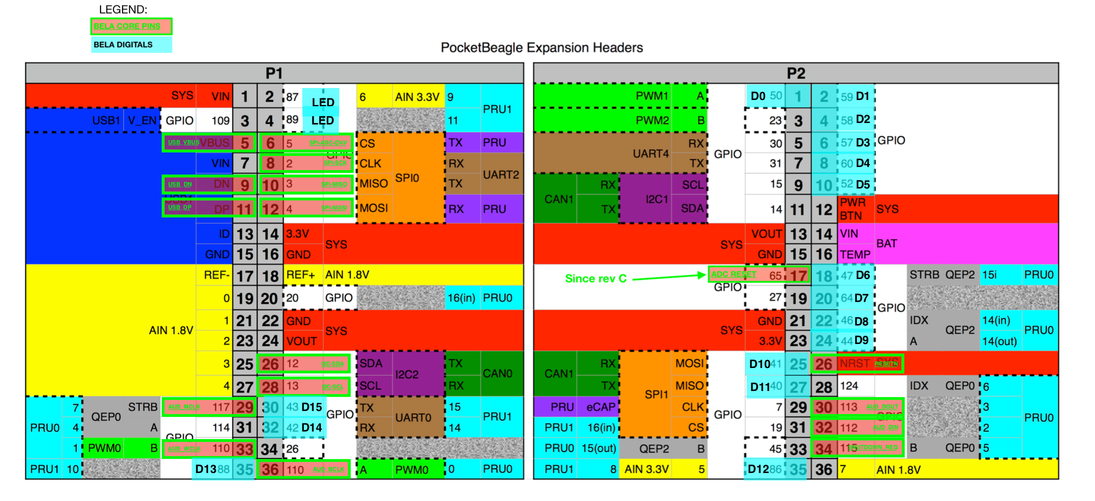
So, I ran your code (this commit: 05571b259976a493fb7a9392ea028d6c52a7cbc0) on the board and hooked up pins P2.25, P2.27, P2.29, P2.31 to scope.

What I see is that:

  • each transmission transmits 8bits
  • the bit clock rate is effectively 24MHz
  • between the CS line going down and the start of the transmission there are about 3-4us
  • between the end of the transmission and the CS line going up there are about 1.4us
  • in between transmissions, the CS line stays high for about 37us
    (the above are typical values, but things get worse in some cases, e.g.: when the thread is preempted)

So, ultimately, the bottleneck is not in the clock speed of the transmission itself, but mostly the dead time before and after the transmission.

There are ways this could be improved by packing multiple bytes in a single transmission, or in a single ioctl() (see e.g. the DEV_HARDWARE_SPI_Transfer() function in dev_hardware_SPI.c), but how this can be done depends on the characteristics of the device: can it use larger words (e.g.: 32bit)? can it receive several words within a single chip-select cycle?

See more details on what parameters to pass to the ioctl here.

I am a bit surprised by the large overhead that comes with each transfer, but I cannot see where the device could be configured to perform better, and in fact I tried the library I linked above and it performs exactly the same : in a tight loop it takes about 40us per each 8-bit transaction.

I believe I'm now getting 54 frames per second, sending 4096 size ioctl calls using 24MHz. If I set to 2Mhz, the rate falls to 5 frames/sec. I think this should more than good enough to do what I want, so I'm going to move forward with this configuration. I haven't been able to find a graphics library that uses a buffer so my thinking is to convert this demo code into a library so I can write to a buffer first, then update the screen as needed.

Appreciate all the help!

BTW, I checked in new code with the changes I made using a buffer, and sending the entire buffer at a time.

I have run into a problem. Supercollider causes my OLED SPI demo to stop. I can reproduce this problem by running the LED blink sc example. If I set s.options.numDigitalChannels = 1, then my demo doesn't display anything, though it continues to run. If the demo is running at the time you start the sc eample, the display goes blank (turned off or all black). If I use s.options.numDigitalChannels = 0, the demo runs fine. I see a small glitch in the animation when it starts, but it still completes.

Why supercollider interfering with my OLED SPI example?

Does the same happen when running a C++ Bela project?

Yes, the C++ passthrough example, if running, prevents the demo from showing anything on the display. And if I turn disable digital from project settings, the demo app works fine.

Ok, can you please detail all the pins that are connected to the display?

Vcc => P1_14 (shared)
Gnd => shared
DIN => P2_25
CLK => P2_29
CS => P2_31
DC => P1_30
RST => P1_32

I guess i thought that since P25 and P27 are also Digital(10/11), and I'm using those for SPI1, that using other digital pins should work. But now re-reading (https://forum.bela.io/d/978-using-an-oled-128x128-rgb-with-belamini/10), I think you are saying when pings are assigned as GPIOs, bela will take them, but since I assigned to SPI bela won't. So I see how P1_30 and P_32 aren't available to me.

So as far as finding new GPIOs, I think I've used them all up. I'm currently using 6 for the LCD, 1 for the bluetooth enable, and UART4 takes away 2.

UART4 RX - P2_5 GPIO_30
UART4 TX - P2_7 GPIO_31
LCD E - P2_03, GPIO 23
LCD RS - P2_19, GPIO 27
LCD 4 - P1_31, GPIO_131
LCD_5 - P2_17, GPIO_65
LCD_6 - P1_34, GPIO 114
LCD_7, P1_20, GPIO 20
BT_E, P2_28, GPIO 116 (BTW, the diagram says it's 124, but 116 works for me, maybe it's wrong)

In the end, I won't have both an LCD and OLED screen, but during development it's helpful to have both. I think P1_3, P2_9, P2_11, p2_33 should be available based on the diagram, but config-pin gives me errors. Maybe that means I have to do some overlay voo-doo, but am I missing any available GPIOs?

    PaulELong I guess i thought that since P25 and P27 are also Digital(10/11), and I'm using those for SPI1, that using other digital pins should work.

    that only works because you have changed the pinmuxer for those pins, so that their electrical signal is no longer connected to the GPIO peripheral, but to the SPI peripheral.

    PaulELong I think you are saying when pings are assigned as GPIOs, bela will take them, but since I assigned to SPI bela won't.

    that one!

    think P1_3, P2_9, P2_11, p2_33

    P1.3 is a bit of a special pin, leave it alone!
    P2.9 and P2.11 both work for me:

    config-pin P2.9 gpio
    config-pin P2.11 gpio

    P2.33 indeed doesn't work, and the reason is that we (probably mistakenly) disable the cape. This can be rectified if needed.

    Do P2.9 and P2.11 not work for you? What error do you get? Maybe you are using i2c-1 ?

    @PaulELong

    Hold on, I realized why it works for me and it doesn't work for you: I actually have P2_09 and P2_11 commented out in my dts (for whatever reason, maybe related to something that happened earlier in this thread).

    so you could try applying this patch to the file /opt/bb.org-overlays/src/arm/BB-BELA-00A0.dts:

    diff --git a/src/arm/BB-BELA-00A1.dts b/src/arm/BB-BELA-00A1.dts
    index 69ab609..f86e5c9 100644
    --- a/src/arm/BB-BELA-00A1.dts
    +++ b/src/arm/BB-BELA-00A1.dts
    @@ -19,12 +19,9 @@
            fragment@0 {
                    target = <&ocp>;
                    __overlay__ {
    -                       P2_09_pinmux { status = "disabled"; };
    -                       P2_11_pinmux { status = "disabled"; };
                            P2_26_pinmux { status = "disabled"; };
                            P2_30_pinmux { status = "disabled"; };
                            P2_32_pinmux { status = "disabled"; };
    -                       P2_33_pinmux { status = "disabled"; };
                            P2_34_pinmux { status = "disabled"; };
                            P1_05_pinmux { status = "disabled"; };
                            P1_06_pinmux { status = "disabled"; };
    @@ -156,10 +153,9 @@
                    target = <&i2c1>;
                    __overlay__ {
                            pinctrl-names = "default";
    -                       pinctrl-0 = <&i2c1_pins>;
    
                            status = "okay";
    -                       clock-frequency = <100000>;
    +                       clock-frequency = <1000000>;
                    };
            };
    
    @@ -251,6 +247,8 @@
                            P1_30_pinmux{ pinctrl-0 = <&P1_30_bela>; };
                            P1_02_pinmux{ pinctrl-0 = <&P1_02_bela>; };
                            P1_04_pinmux{ pinctrl-0 = <&P1_04_bela>; };
    +                       P2_09_pinmux{ pinctrl-0 = <&P2_09_i2c_pin>; };
    +                       P2_11_pinmux{ pinctrl-0 = <&P2_11_i2c_pin>; };
                    };
            };

    This does the following:

    • avoids disabling P2_33_pinmux (which was a mistake, as mentioned above)
    • Instead of disabling the P2_09_pinmux and P2_11_pinmux, it just sets its default values to be i2c. Then via config-pin you can still change their behaviour to make them gpio. The downside of this is that I don't think it would work straight away on a BeagleBone, but it should work well for your purposes.
    • avoids telling the i2c-1 bus to own the pins (as they will already be set by the P2_xx_pinmux entries)
    • bonus: increases the speed of the i2c-1 bus

    After you apply the patch (either manually, by removing the lines marked with a - and adding those marked with +, or using patch or git apply), then to apply these changes you would do:
    - rebuild the dtbo:

    make -C /opt/bb.org-overlays 

    (if this does not output this line DTC src/arm/BB-BELA-00A1.dtbo, it may be that the date is not set correctly on the board and so the file does not appear to have changed to the make building system. In that case, simply delete the output file with rm /opt/bb.org-overlays/ src/arm/BB-BELA-00A1.dtbo and try again).

    • install it in the system location
      make -C /opt/bb.org-overlays installl
    • then reboot and you should be able to use config-pin again

    Success! I can now control P2_9, P2_11 and P2_33 while bela is running C++ app or my code. Attached a gif (animated, but I don't think that it works on the site) which shows a demo app running. It's redrawing the screen each time and sending as one big buffer 23 times a second (if my calculations are correct).

    alt text

      great!

      PaulELong Attached a gif (animated, but I don't think that it works on the site)

      I noticed the same thing today. The solution was to go to imgur, upload it manually (no need for an account), then get the url by clicking the "get share links"

      Sorry it turns out my instructions were wrong, I amended your post. It turns out that imgur has "images" or "posts" and sharing one is different from sharing the other.

      That is very, very cool! Thanks for blazing the trail.

      Now that this is getting real, time to ask some questions!

      • What's the latency/frame rate now?
      • What's the CPU overhead for running this? I assume it's related to how often the image is changed (e.g., any change to a framebuffer requires resending all the bits on the bus, a static image needs no refresh)

      Would love this capability to be baked into bela someway. Having a display is a common feature. But given that it only works on the Bela mini makes that less appealing. Still even having a slow display for the non-mini bela would be useful. Wonder how fast this could go without the hardware assist.

      The OLED is 128x128 waveshare.

      My frame rate is 23 frames/sec. I haven't thought about latency yet or how to test it. Also the only testing with load so far is running the my OLED demo with the passthrough example. My next step is to integrate it into my harmonizer project, which will tell me what happens in a real-time scenario where latency will be a factor. I can try to figure out a way to measure latency/cpu load more directly, but my guess is you are right, and it will be related to how often you update the buffer. The OLED I'm using has a way to write any rectangle area, so updates could optimized to maximize the redraws.

      As for baking it in, I think I2C is an option. The original waveshare demo supported SPI and I2C, and was targeted at some other platforms using flags. I added a BELA and the associated code. So my guess is that with the I2C version is pretty easy to create.