ryjobil i also found some forum messages (have to dig up where) suggesting a 10 band multipole filter (instead of 10 bandpass filters) on both carrier and modulator with autoadjusted q (is this even a thing?) would be more processor friendly...

i don't see how that would be better then 10 bp filters, but maybe you know :-)

ryjobil In the current code these can be manually assigned as my prior instructions suggested. Q = fc/BW. The main interest in frequency sweep and/or step response data is to get an estimate of filter order used.

yeah, got that. i just thought i would write those numbers down, for reference. i read through the manual and in the filterbank section "very" steep filter response is mentioned which would suggest 4th order at least. looking forward to do those measurements!

ryjobil

That's good info about the impulse vs. step response, thanks for sharing. Of course it's never as easy as what the theory says - makes sense that because your impulse can't be infinitely high the results will be different than expected. Most of the time to see the shape of a filter I just use a saw/square wave.

Regarding the ZDF stuff, my main resources for implementing them in C++ were "The Art of VA Filter Design" (free PDF) and Will Pirkle's app note 4 (https://www.willpirkle.com/app-notes/). Below is a screenshot of the state variable filter block diagram, difference equation, and a breakdown of the different digital integrators. Essentially, ZDF uses the bilinear transform instead of forward or reverse Euler which approximates the area under the curve more accurately. The result is a "smoother" sound that responds better to modulation than a biquad.
alt text

alt text

I'll make a dedicated thread about it later where I'll post my code, but if you're curious about how to implement it in the meantime here's a link to a GitHub of some Mutable Instruments code that shows how to implement 1 and 2 pole ZDF filters. Ironically I found Olivier's code months after I had come up with my own way of doing it in C++. It was pretty vindicating to find out we did it very similarly!

https://github.com/jakplugg/stmlib/blob/master/dsp/filter.h

Cheers

@matt Thanks for the teaser 🙂. This stuff will be really useful for refactoring my envelope filter SVF. I 2x oversampled the naive chamberlin SVF to overcome the stability problem, but the ZDF approach will definitely reduce CPU usage on that one.

Based on Oliver's code, I see 7 MUL, 4 ADD, 3 SUB, which is going the opposite direction I need to go. This is efficient when you want to have arbitrary access to any or all of the 3 outputs of the biquad structure, but that isn't needed in a vocoder.

Here's a bonus for what I have come up with for the envelope detector to improve efficiency in the EVD section:

//
// Lazy RMS detector
//  Inputs:
//  sz = processing block size
//  x = input signal (typically AC waveform)
//  y = detector state variable (current RMS measurement)
//  k = integration time constant, typically (1/RC)*(1/Fs)
//
void
lazy_rms_detector_tick(int sz, float *x, float *y, float k)
{
    int i = 0;
    for(i=0; i < sz; i++)
    {
        y[i] += k*(x[i]*x[i] - y[i]*y[i]); // Forward Euler integration, resolves to sqrt((1/k)*integral(x*x))
    }
}

It gives me sqrt() function and averaging in a single shot with 3 MUL, 1 ADD, 1 SUB

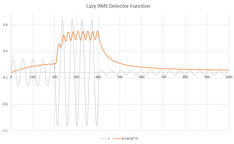
The basic principle is that in an envelope detector you already want a slow/averaged response. Time required for this algorithm to resolve on sqrt(x) can be tuned with constant "k". I call it a "lazy" RMS detector because it lazily iterates the sqrt() solver at audio sample rate and "gets there when it gets there".

The time to resolve represent the desired averaging (attack/release times).


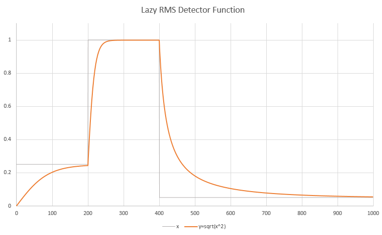
Below we see slow time constants for low signal amplitudes and fast time constants for large signal amplitudes (exaggerated here to demonstrate the effect). Would use longer time constants in a real application to reduce ripple. A second-stage smoothing filter might also be a good idea.

  • matt replied to this.

    ryjobil

    Yes, now that I think about it the state variable filter doesn't make sense for a vocoder because the bandpass response you get it actually only 1 pole. The benefit is having three simultaneous and related filter outputs but that's not important in this application.

    That being said, you can adapt any filter structure to be ZDF, so maybe a ladder style bandpass or some other filter topology adapted to ZDF would be ideal for an efficient vocoder.

    I like your "lazy" approach! My envelope detectors use SVFs and a rectifier (absolute value) and are CPU hogs but I can control the damping and cutoff of my control signal which returns some interesting results. Anyways, I'll post that code soon enough!

      matt My envelope detectors use SVFs and a rectifier (absolute value)

      I made an analog envelope filter about 12 years ago (has it really been that long?) that was using an SVF with a pot to control resonance and FC on the detector, and as you pointed out -- some interesting results in the control signal.

      As a side-note the lazy RMS detector could be increased to a second-order response if you purposely wanted to add the oscillatory response to it. This would be just one more MAC (so 4 instead of 7 from SVF). I developed this detector structure using analog circuit design techniques, prototyping it in LTSpice. I digitized using both bilinear transform and forward Euler integration, and found forward and/or Euler worked well enough that the extra CPU cycles required to realize the BLT structure weren't justified (step responses look identical and you only see a difference as you approach the stability limits). As would be expected, the BLT version is much better behaved near instability, but instability happens at fast enough convergence times to be impractical for its intended function -- so the practical use of the circuit automatically dictates that it does not operate near instability.

      On the topic of more "interesting" envelope detectors, this one was inspired by a design by Harry Bissel (link and information in comments in source code):
      https://github.com/transmogrifox/Bela_Misc/blob/master/vocoder/envelope_detector.cpp

      I assume you're still working on your own Vocoder -- I'm definitely interested in seeing that when you are done. These things are just a lot of fun 😃

      hmm, i tried my mam vf-11 side by side with an ehx v256 at louder levels today and the mam is very feedback prone once things get a little louder. but it sounds fat! the ehx is very feedback resistant but being an fft vocoder (i assume) it sounds a bit dull and washed in comparison.

      do you think a digital recreation of the bp filter vocoder will also be so feedback prone, or are there tricks to avoid that? (apart from a "nearfield" mic)

      The short answer is yes, I think we can make it less feedback prone.

      I found the VF-11 manual and it looks like it has a compressor in the mic (analysis) input but no user controls for the compressor. A dynamic range compressor definitely has the propensity to increase feedback because the gain will be higher for small amplitude signals.

      If the compressor is the reason for feedback, then a digitization of the response has two advantages:
      1) We can make compressor params adjustable, and make it possible for the user to bypass it altogether.
      2) We can add a noise gate.

      The compressor code I used is fully adjustable, I just need the time to hook Analog inputs (for pots) into the code to expose these to the user.

      You can see pieces of a noise gate in the works in the code (currently commented out). It's partially implemented but needs some work to fully develop it.

      great! the mam has a noise gate as well, but i suspect it is on the output rather then the input

        a year later

        Hi, I'm very interested to make this vocoder. Would it run on the mini Bela, or does it require the full version?
        I have done some small bits with arduino/teensy, though new to Bela. Thanks!

          SOOTY It runs on Bela mini without any more limitations on the full size Bela. Notice the Bela mini has the same CPU, so processing power is the same.

          Bela mini also has enough inputs/outputs to run the vocoder. Let me know if you need pointers to hook it up. The code should work without modification as long as you get the hardware connections done properly.

          Let me know if you have troubles and I'm happy to help. I have a Bela mini, so I can work out the kinks if there are any.

          Thank you so much, very kind. I will let you know how I get on.