• Audio
  • Using analog outputs for Audio

Hey all,
I'm doing a project where I'm using the Bela running SuperCollider for multi-channel output. And I'm looking into using the analog outputs to generate multichannel audio.

When I tried using the audio directly from analog0 (just playing some sine tone tests) I noticed it was extremely distorted. Then I took a look at the signal on a scope, comparing the same signal played on analog0 and audio0 simultaneously.

The test results might be useful to some of you, you can check them out here:
http://jonathanreus.com/2016/09/06/bela-io-tests/

Anyway, there's lots of digital stepping happening on the analog0 output, which shouldn't be a surprise since it's running at 22.05kHz and, as far as I understand, utilizes a DAC unit that's not optimized for audio applications.

My question is: to utilize the analog outputs for audio, what kind of filtering electronics would you recommend adding? Would a simple passive RC low pass filter be enough? Or should I use an active filter or some kind of passive RC / buffer combination?

Many thanks!
Jonathan

Hi Jonathan, there are three separate issues to consider with the analog outputs:

1) Clipping. The biggest source of distortion in your plot is that the top is clipped. This is because the DAC can output up to 5V but if the BBB is powered from USB, the supply rail is often a little lower (around 4.7 or 4.8V). Reduce your maximum amplitude and that part will go away.

2) Stair-steps (high-frequency aliasing). Actually these are less of an immediate audible problem than you might think, despite the look, because they are mainly creating distortion products in the ultrasonic range. Still, you can reduce them with some low-pass filtering, as we do on the audio expander capelet. You can find the schematic for that here: https://github.com/BelaPlatform/bela-hardware/tree/master/capelets/audio_expander. But a simple first-order RC will be a start.

3) Nonlinearity. It turns out, we recently discovered, that there's a really odd behaviour in the DAC where the settling time (i.e. the shape of the stair-step) changes depending on what code the DAC is set to. Certain codes settle quickly, others settle slowly, in a way that's quite demonstrably repeatable on different chips. When used at a regular sample rate as we do, this leads to a subtle warping in the average value of each sample, which creates distortion products that are worse at lower signal amplitudes.

I'm working on a mathematical model of the distortion now, after which I am going to try to add a compensation feature in software. No matter what, the extra DACs won't ever be quite the same audio quality as the main codec, but they should get fairly close.

    7 days later

    Thanks Andrew, for the thorough response!

    So to remedy the supply rail distortion, a rule of thumb would be to always multiply your output signals by 0.9 to be safe?

    Even audio quality fairly close to what comes out of the main stereo outputs is still ample. :-)

    4 days later

    I have one of the new Audio Expanders here on my desk now, hooked up to the scope. :-)

    It looks like you can go up to about 0.95 without running into the supply rail. If you go above that, the signal may be clipped. I am powered by USB; it might be better from the barrel jack. If you clip the signal, it's even worse than just getting harmonic distortion, because the 5V rail is very noisy if it ends up "raw" in your output, even for a short time.

    I'm going to put some command-line switches to enable treating analog channels as audio, which do this kind of rescaling and shifting, plus (in the case of inputs) DC-blocking. Keep an eye on the dev-capelet branch in the next week.

    Thanks Andrew! It'll be great not to have to worry about the rail distortion. :-)

    Continuing the original discussion. I'm making some progress with the project. The plan now is to develop a little capelet specifically for wearable sound & instrumentation measurement / with output filters on the analog outputs and some built-in class-D amplifiers that can deliver more power to multiple transducers/speakers.

    I'm basing the output filter circuits on those found on the audio capelet. But I'm noticing that the ADD8704 op-amp you used is no longer produced. I'm looking at the EL5420 - but my EE chops are amateur at best - would you recommend using this op-amp?

    https://github.com/jreus/wearable_cape_v01/blob/master/Documentation/Datasheets/el5120-220-420-opamp.pdf

    Also a related question, is there any reason not to use more standard value resistors in the filter? I ran a simulation with the EL5420 using 18K and 10K resistors and was able to get a cutoff around 17303Hz.. which seems reasonable to me, but again my EE knowledge has lots of holes!

    https://github.com/jreus/wearable_cape_v01/blob/master/Documentation/Low-pass-filters.png

    The ADD8704 is just for the EAGLE footprint. In the BOM, the actual part is OPA4348. Many parts will work, an important feature being rail-to-rail I/O.

    You can use standard 5% resistors without much change, with just a bit of error in the cutoff frequencies. When building in quantity, it's just as easy to get E96-series 1% resistors, but the difference isn't that big.

      a month later

      andrew hey Andrew, one more question that's maybe also valuable to others.

      I'd like to run the analog outputs from the Bela to a line input. Since the Bela's outputs send 0-4.7V, I'd like to attenuate the signal to 3V peak-to-peak. My naive approach to this would be putting a voltage divider before the filter to attenuate the 4.7V signal. Do you think this is a bad approach?

      Long answer to a simple question: you have three options, all with tradeoffs:

      1. Put the voltage divider before the filter. The problem here is that the input to the filter on the capelet is designed on the assumption that the output is a zero-impedance source. That's not perfectly true since there is a 220 ohm resistor on the cape for protection, but anyway, if you add a high-impedance voltage divider, the filter response will end up way off.

      But actually you have a simple option: hang a 390 ohm resistor between each analog output and ground. This will form a voltage divider with the 220 ohm resistor already on the cape, reducing the gain by 36%. (The ratio you need is 1.76:1, or approximately 1.8:1). Actually it will make the filter response slightly more accurate than before, since the source impedance goes from 220 ohms before to 220 // 390 = 140 ohms after. The tradeoff is that the low resistance wastes power, about 8mA per output in the worst case. The DAC is rated for 30mA, so it's probably okay, but together the power draw could lead to a slight temperature rise in the DAC, but probably well within spec.

      1. You could put a divider at the output of the filter instead. Again you want the bottom resistor (the one to ground) to be 1.76x as large as the top one. For example, you could use 2.2k (top) and 3.9k (bottom). The downside is that the accuracy of this arrangement depends on the input impedance of whatever you connect it to. If your mixer (or whatever) had an input impedance of 100k, it wouldn't matter too much. If the input impedance was 10k, then the attenuation would be way off. The smaller you make those resistors (e.g. 220 and 390), the less it will matter, but you get back to the wasted power problem, now borne by the op-amp instead.

      2. You could just scale down the values digitally and don't do any circuit changes. You lose about 4dB of SNR, and you are no longer guaranteed by hardware to be limited to 3V max if there's a problem in the code, but you save some circuitry.

      7 days later

      Can I hijack this thread to ask about analogue output levels?
      I notice when using an analogue out for audio, it is MUCH louder than the main audio outs.
      It sounds very distorted although this could be to do with me getting the AC coupling wrong.
      I want to rule out the cause as being purely the high level.
      Should I use the DAC level in the project settings to compensate? or should I turn down the audio level in my own code? Or should I not worry about it.
      The output is not clipping my mixing desk but it's very distorted for some reason.

      What values are you writing to the analog out? Analog I/O are to be kept in the range 0:1 while audio I/O is in the range -1:1. If you try to write to analog outputs a signal in the range -1:1, the negative part of the wave will be clipped to 0, resulting in harsh distortion.
      See [here(https://github.com/BelaPlatform/Bela/wiki/Using-the-Audio-Expander-Capelet#working-with-raw-signals-c) for more info.

      To check if your code is generating distortion, try to feedback the analog out into the audio in (some male to female jumper cables will do the trick) and digitally route the audio in to the audio out, then listen to the audio output. This should be ok, especially if you reduce the input gain (PGA) of the audio inputs.

      Ah I will check it out.....
      so basically divide by 2 and add 0.5 before going to the output.
      thanks

      Yeah, just to avoid clipping at the top in case your power supply provides a bit less than 5V, maybe multiply by 0.48 instead of 0.5.
      Alternatively, you can just enable the audio capelet command line options from the GUI in the IDE to obtain the same effect transparently in the background.

        a year later

        Hu hu indeed it worked well. Thx all

        I know this is old, but I thought I would add this about filtering the analog outputs. @andrew mentioned more than a year ago that the stair-stepping is in the ultrasonic frequency range and inaudible.

        While this may be true, there are 2 things to keep in mind:
        #1) Shannon's sampling theorem: You can perfectly reproduce any original band-limited signal at 1/2 the sampling rate. In other words, your maximum bandwidth from a 22.05 kHz sampling rate is about 11 kHz. What comes out of the ADC is the audio signal modulated onto a pulse train. The same image repeats every 22.05kHz, spanning 11.025 kHz above and below, starting at 0 Hz. The 0 Hz to 11.025 kHz image is what you hear...nominally.

        Anything between 11 kHz an 22.05 kHz is noise, and this is not what I consider ultrasonic. 22.05 kHz down to 11.025 kHz is a mirror-image of every thing from 0 Hz to 11.025 kHz.

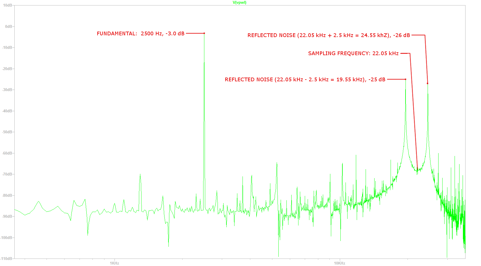
        As an experiment, play a 6 kHz tone out of the Analog Output back into the audio input (which is sampled at 44.1kHz) and look at the FFT. You will see a tone at 6 kHz and a tone at 16.05 kHz in the spectrum.


        #2) Class D amplifiers and/or filters with long transient response:
        If the ultrasonic noise remains in the signal it can still be modulated with other high frequency noise sources to create cross-product terms that ARE audible. Class D amplifiers will have a switching frequency that is unlikely to be a perfectly synchronized multiple of 22.05 kHz. Any difference will create both inaudible and audible tones in the output spectrum.

        Filters with long-duration transient responses also have an opportunity to create audible cross-products if there is any amount of nonlinearity in the following amplifier stages high frequency range.


        The best thing to do is to create an output filter that has fairly good stop-band rejection at 11.025 kHz and above.

        Practically speaking, this indicates a filter cut-off at 6 kHz to 8 kHz, depending how aggressively you want to filter the output and how many stages you use.

        For example, a 6th-order low-pass with 5.5 kHz cut-off will yield (6 order)*(-6dB/octave) = -36 dB rejection at 11 kHz, and -72 dB rejection at 22 kHz (comparable to 12-bit SNR).

        Ideally one would aim for -90 dB rejection at 11 kHz to maintain 16-bit SNR levels, but as you can see, that would require a 16th order filter at 5.5 kHz, or much higher order filters if you want more bandwidth.

        This is the trade-off, but any amount of filtering is an improvement. The advantage with audio signals is typically the relative amplitude decreases with increasing frequency, so practically speaking you will take care of most of the noise if you have good rejection within 5 kHz of the sampling rate (in this case, good rejection at about 17 kHz).

        As for filter design, the Multiple Feedback structure maintains the best high-frequency characteristic (the Sallen-Key structures start to do unexpected things at higher frequencies due to op amp characteristics). The multiple feedback filter design is pretty straightforward with easy-to-find online calculators. One such example is here:
        http://sim.okawa-denshi.jp/en/MultipleFB3Lowkeisan.htm

          I simulated this and created an FFT of the output as a proof-of-concept about what happens between Fs/2 and Fs.

          A 2.5 kHz sine wave was synthesized using a zero-order hold output to generate a piece-wise linear (PWL) file which was imported into LTSpice. The LTSPice FFT function was used to evaluate the FFT.

          The reason for doing this in LTSPice is so that this synthesized DAC output file can be used to evaluate analog filters in the circuit simulator.

          Here is the image, marked up with what I was attempting to explain in words in the prior post:

          andrew 2) Stair-steps (high-frequency aliasing). Actually these are less of an immediate audible problem than you might think, despite the look, because they are mainly creating distortion products in the ultrasonic range. Still, you can reduce them with some low-pass filtering, as we do on the audio expander capelet.

          Note the Audio Expander Capelet has a cut-off at about 22 kHz, so it doesn't even touch the stuff between 11 kHz and 22 kHz. From above, you can see this stuff will be audible so more aggressive filtering is needed to clean it up.

          LTSpice simulation file can be found here:
          https://github.com/transmogrifox/Bela_Misc/tree/master/Analog_Output_Noise_Demo
          Download everything in that github directory into a directory on your computer and run the .asc file with LTSPice (free download from Linear Tech).

          giuliomoro

          Do we also have to multiply by 0.48 and add 0.5 when using the analog outputs in SuperCollider?

          In SC on the Bela we have the option to treat the analog outputs as audio busses using the server config option:
          s.options.numOutputBusChannels = 10; // use stereo out + 8 analog outs as audio busses

          I had assumed this would do the same auto-scaling & ranging that the audio capelet command line option provides from the IDE. Giulio, can you confirm this?

            ryjobil Thanks for this explanation! I'm sending signals from the analog outputs to a class-D amp and there is indeed a noise problem - which remains a mystery. Your observation might be another point of investigation. :-)

            In my case the noise manifests as an audible tone (and some CPU noise) at around 2766 Hz, which pitches up and down proportionally to the block size.

              jonathan The noise you describe sounds like something different, possibly something coupling in through the power supply.

              I have had an irritating noise related to block size also due to a software bug where I had one of those "off-by-one" errors in one of my loops, which failed to write a sample in each block. It didn't seem to matter whether there was audio or not, this tone was audible. Once I tracked it down the tone went away.

              The noise I'm talking about in the other post is proportional to the audio signal and would show up as degraded audio quality. With sufficient output filtering you could have reasonably high-fidelity audio up to about 5 kHz. It may be in your application the effort required to make high-order filters may not be worth it.

              At the very least a simple R-C filter with cut-off at around 7 kHz would be a good idea. This would cut most of the noise in half. A further improvement would be to set a 2nd-order low-pass filter at 7 kHz on the DSP side before you send it out the port.

              In the end the main point I am trying to make is that stair-step noise from an un-filtered 22.05 kHz DAC is not entirely ultrasonic and you will get some audio quality improvement if you have good filtering above 11 kHz.