• Audio
  • Controlling voice coils with Bela

the digital outputs will generate "squared" signal between 0 and 3.3V: the signal will only assume the value of 0 or 3.3V.
The analog outputs will generate "DC-coupled" analog signals between 0 and 5V: the signal will assume all the values in the range.
The audio outputs will generate "AC-coupled" analog outputs between about -1V and +1V: the signal will assume all the values in the range.

Yours is an "audio amplifier": this means that it will probably be AC-coupled and so any of the sources above will be suitable for driving it. The amplifier itself is class D, so it will produce a PWM output, but that doesn't mean you should feed it a PWM or a digital input: this is just an implementation detail, that you shouldn't be concerned about. All you should care about is : you can feed any analog audio signal input (and a digital signal at audio rate, like the Bela digital I/O, is just a special type of analog signal, as far as any amplifier is concerned), and the amplifier will try to reproduce it as best as it can at its output.

The digital outs will be more limited in that they cannot represent a large number of values, but only two, however this may be sufficient for your purpose. Depending on how limited the bandwidth of your output signal is, you could consider using "soft-PWM" on the digital outputs to obtain effectively a wider range of dynamics from those. This would be similar to the principle used by class-D amplifiers: it's simply another application of the same concept. As such, it would work with any type of amplifier (including, but not limited to, class D).

Hi,

Thanks a lot for your very clear answer. I understood that I can use either analog or digital output (as digital is a particular case of analog) to feed the class D amplifier, which will output a PWM signal.

As I would like to generate mainly white or pink noise, I think that the bandwidth is not an issue for digital outputs. Am I correct ?

Thanks in advance,
Quentin

    well, each of the digital outputs can be used as a "1-bit/44.1kHz" audio output. I wouldn't imagine audio rate white or pink noise to be achievable with that, however I also don't think that's required for a haptic application: my understanding is that humans can only perceive haptic vibrations up to 1kHz or something like that, so you could actually use the digital outs to generate a PWM signal with carrier frequency of 44.1kHz/32 = 1.37kHz and have log2(32) = 5 bit resolution. This should allow you to get some meaningful vibrations with some degrees of dynamics control.

    Indeed. However I think that it is possible to produce a pseudo white noise "between 0 and 1kHZ", by having a constant power spectral density between those frequencies. I have been told by an haptic expert than this is more realistic than a simple vibration at a given frequency.

    Your answer is really, really helpful. I have read a lot to understand it, can you please tell me if the following is correct :
    - The carrier is the triangular wave used to generate PWM signal
    - If the carrier frequency is less than the input signal "maximum frequency" (here 44.1kHz), then we have "more space" within a period to go up and down the carrier, and therefore increase the resolution of the duty cycle.
    - If the carrier frequency is really close to the input signal, the resolution will be very low, but the output can have a higher frequency.
    - So we need to find a compromise between output frequency and resolution.
    - In your example, I can output a PWM which will be averaged to a 1.37kHz signal with 32 discrete possible values.

    Sorry for using non-technical words but this is really not my field, and thanks a lot for your time even if this is beyond Bela topic.

    The Nyquist sampling theorem applies here. If you have a PWM resolution of 32, then the maximum frequency you can reproduce without aliasing is 689 Hz. In reality the PWM fundamental is mirrored off of every 1.38 kHz, so you technically need a brick-wall filter with 689 Hz cut-off for any of the cross-terms to go away. If you increase PWM rate but decrease resolution, then the quantization noise becomes more prominent. The extreme case is reducing resolution to 1-bit....so here is an example of a 1-bit DAC for this application.

    You mentioned a noise spectral density to be more desirable/realistic anyway, so here's an example...

    You can do noise shaping with a filter. I have checked in a proof-of-concept here:
    https://github.com/transmogrifox/Bela_Misc/tree/master/Noise_Shaping

    Rather than PWM this creates a pulse-density-modulation, which does not have a prominent peak at the PWM frequency. You can see below the harmonics of the 1 kHz filter center frequency due to the 1-bit sampling quantization noise effect.

    Basically use the rand() function to get reasonably flat noise spectrum and then filter that with a biquad IIR filter (code included in case you are thinking "IIR what?".

    Generating the 1-bit signal boils down to this one little function:

    // Shaped noise, 1-bit sampled
    // Produces prominent peak at filter cut-off
        // Gain parameter currently not implemented here
        // The implementation would be to strobe this function on
        // and off to make total output power adjustable
    float randseq_tick(float gain)
    {
       // Run the band-pass filter
        r_duty_f = run_filter((float) (rand()%2048)/2048.0, nf);
    
      //1-bit sampling:  If > 0, output is 1.0 (logic high)
    // if <=0, output is 0.0 (logic low)
        if(r_duty_f > 0.0)
            return 1.0;
        else 
            return 0.0;
     
    }

    The rest of the code is preparing several traces of raw data and performing the FFT on it to output something I can plot in Excel.

    In the end this is the spectrum you would get if you ran this algorithm sample-by-sample and output at 44.1 kHz sample rate to a digital output:

    Lowering the filter Q will spread the noise spectrum more, while increasing Q will narrow it at the filter center frequency.

    If you look at the Excel spreadsheet in the github repo you will see in the time domain the high-Q filtered output looks like a 1 kHz square wave. It takes a closer look to see it's a 1 kHz square wave with significant jitter.

    The output with filter Q of 1.0 looks more random, but you can see there is a correlated pattern to it.

    You might find in your application all you need is to output a squarewave at some frequency with integer multiples of the sampling period.

    The filtered noise approach will center the peak of the noise hump right at your desired output frequency, giving you all of the in-betweens.

    If you need amplitude modulation on this then you apply PWM to the 1-bit modulator output to lower its overall signal power. This will mess up your spectrum but it may be acceptable in your application. Better to do variable-frequency PWM rather than fixed frequency PWM, that is, you skip "M" pulses every "N" pulses to get gain 0.5 to 1.0. You invert this to get gain 0.0 to 0.5, e.g. you mask "M" pulses every "N" pulses.

    This method lets you continuously trade off bandwidth for resolution as the signal's requirement for dynamic range increases away from 50% duty cycle.

    First of all, I don't know how to thank you for taking such time to answer.

    The Nyquist sampling theorem applies here. If you have a PWM resolution of 32, then the maximum frequency you can reproduce without aliasing is 689 Hz.

    This part is now clearer in my mind. The carrier frequency is like a sampling rate, so the maximum frequency of the analog signal that we are "sampling" with PWM must be half the sampling rate to avoid aliasing. Yesterday I mixed up the analog output signal frequency (after passing through the low-pass filter, in my case the speaker) and the carrier frequency.

    In reality the PWM fundamental is mirrored off of every 1.38 kHz

    Do you mean that there is a 1.38kHz frequency component in the output frequency spectrum - that does not exist in the input signal ? Is this because the switching frequency is fixed ?

    If you increase PWM rate but decrease resolution, then the quantization noise becomes more prominent. The extreme case is reducing resolution to 1-bit.

    I understand that decreasing resolution is by definition representing less discrete values in the filtered analog signal. With 1-bit resolution we can either represent logical low or logical high, right ? So a 1-bit DAC is the same as PDM, but a PWM with 1-bit resolution would give nothing but a two-state analog output after being filtered by a low-pass filter ?

    You can see below the harmonics of the 1 kHz filter center frequency due to the 1-bit sampling quantization noise effect.

    I have read that 1-bit DAC are very common nowadays, even high-end devices. Why is there a lot of quantization noise in that case ?

    Also, thanks a lot for your code. I'll test it as soon as I receive the Bela. I need more time to figure out what does a biquad IIR filter.

    If you need amplitude modulation on this then you apply PWM to the 1-bit modulator.

    As this is what a class D amplifier does, I think it is suited for this, am I right ?

    Thanks again.

      Chosto Do you mean that there is a 1.38kHz frequency component in the output frequency spectrum - that does not exist in the input signal ? Is this because the switching frequency is fixed ?

      This is correct. You would see this directly on an oscilloscope. To exactly meet the conditions of the Nyquist Sampling theorem, a brick-wall filter would be applied at 1/2 the PWM frequency and you would be left with the pure tone. In the real-world you are expecting the speaker to take off this carrier noise, but in your case the 1.38 kHz sampling period is within the band of the coil, so you either have to add steep analog filtering at the output to pull it down if it is a problem in your application.

      Chosto So a 1-bit DAC is the same as PDM, but a PWM with 1-bit resolution would give nothing but a two-state analog output after being filtered by a low-pass filter ?

      PDM and PWM can both be considered 1-bit DACs. PDM takes advantage of noise to evenly spread the spectral density of the quantization error over a wider frequency band. PWM focuses the quantization noise into a narrow band. You can think of PWM as putting all of the pulses of an averaging period into adjacent time slots, where PDM spreads all of those pulses at random intervals. In both cases you can increase resolution by decreasing bandwidth, even though it may initially seem counter-intuitive that you can get 16-bit resolution from a 1-bit DAC.

      A 1-bit DAC like the high-end stuff uses feedback so it adjusts the average output high frequency noise power to match the low-bandwidth signal power. It's sort of like amplitude modulation where the carrier is wide-band high frequency noise. The output pulse train is filtered to remove the high frequency noise The lower frequency cut-off used, the more points used in the averaging, the higher the effective resolution. With a 44.1 kHz bit rate, you're pretty much limited to 2 or 3 bits if you want to reproduce something up to 1 kHz.

      Chosto I have read that 1-bit DAC are very common nowadays, even high-end devices. Why is there a lot of quantization noise in that case ?

      I think my comment above might have addressed this one too. Basically if you look at something changing between 1 and 0 at a really high rate (usually > 20 MHz) you can average it over a much longer period of time.

      Say you have a sequence 10101101. Averaged over 8-samples gives you the value 0.625. As you can see this has 8-bit resolution. To change this sequence into PWM, you have 11111000, which averages to the same level. If you output this sequence repeatedly, you will get one particularly dominant frequency in the output. If you output the PDM sequence 10101101, you will get the same average value but the noise moves to a wider band at higher frequencies.

      Suppose you have a sample at 0.75, 44.1 kHz base sample rate. You can output a sequence of '1' and '0' pulses that average out to 0.75 over the duration of 1/44.1k = 22.68us averaging interval. To get 16-bit resolution you need a total of 216 pulses during that interval, so you need 44.1k*216 2.89GHz pulse rate -- at least, that is what you would need for PWM.

      How does a sigma-delta modulator get 16-bit resolution with only a 20MHz bit rate? This is related to noise-shaping and post-filtering -- the quantization noise is pushed up into the band where it can be more easily filtered off (think of the difference between 11111000 and 10101101). It's hard for me to explain it without pointing you to a paper on sigma-delta modulators, but basically this is focusing the noise into a band that will be naturally rejected by the physical system (output filters and/or speaker).

      Chosto As this is what a class D amplifier does, I think it is suited for this, am I right ?

      Not the way you are thinking. A Class D pulse modulation is usually >500 kHz. You will be feeding it a 1.38 kHz square wave. The class D amp will chop that up, reconstruct it, and output an amplified version of what you put in to your speakers.

      For whatever it is worth, the industry has many names for switch-mode amplifiers (like Class D). These trademark names often refer to some form of PDM/Noise Shaping as compared to classical PWM. I think some variation on PWM is still dominant in higher power amps because switching losses in the FETs would become important, lowering the efficiency of the amp. Fortunately an analog PWM circuit does not quantize the input signal so the resolution trade-off is not an issue as long as the switching frequency is high enough to be rejected by the speakers.

      Chosto Also, thanks a lot for your code. I'll test it as soon as I receive the Bela.

      I'm not certain my code does what you want to do. It's more of a proof-of concept regarding PDM vs PWM and the potential to spread the quantization noise. If you really want to reproduce certain wave shapes this needs to evolve into a some form of a sigma delta modulator because we can push a lot of the noise up >10 kHz.

      If all you want is a variable frequency output with a noise spectrum generally centered around any arbitrary point then my code might do what you want. I'm not very familiar with haptics, nor with your particular application so I'm not sure how elegant of a system is required to do what you actually need.

      I need more time to figure out what does a biquad IIR filter.

      In my code it implements a band-pass function. Noise is used as the signal input, filtered noise is the signal output.

      IIR stands for "infinite impulse response", which means it recirculates some of the output back to the input. Neglecting digital resolution and noise floor it would hypothetically recirculate all inputs from all time forever as the history decays toward zero. In reality the past history decays to <2-32 (or whatever resolution) pretty quickly.

      "Biquad" refers to the filter order, in this case order 2. It means the magnitude @ angle vector associated with the transfer function occupies two quadrants (phase shift limited between 0 to 180 degrees is one way to think of it). In contrast a first-order filter has phase response contained in the first quadrant (0 to 90 degrees).

        @ryjobil Thanks for making so detailed answers. They are very useful. I think that I understood PWM quite well.

        ryjobil PDM and PWM can both be considered 1-bit DACs.

        Is PDM an oversampling 1-bit DAC whereas PWM is "just" 1-bit DAC ? From what I have read, sigma-delta will do oversampling and use each quantization error to adjust next sample, averaging the error (and I believe that this is the way PDM is done, right ?). But PWM can have a sample rate equals to Nyquist rate, and resolution will influence the precision of the samples. If this is correct, hurray. Otherwise I missed something.

        ryjobil The lower frequency cut-off used, the more points used in the averaging, the higher the effective resolution.

        That makes sense for PWM, essentially because I understood that PWM will introduce its own carrier frequency in the output signal if not filtered.
        But I have more trouble to understand averaging in case of PDM. As you said, PDM can be seen as PWM with 1-bit resolution, that is to say fix width pulses. But the averaging must be different here, because if we just put a brick-wall filter with a cut-off of 22.05kHz I highly doubt that my signal will be the one I except. As you said, the average for 8-bit resolution "11111000" or "10101101" is the same. But in the first case (PWM), we know the carrier frequency to filter (and average to get the initial value). What for PDM ? Why not averaging "1010" and then "1101" ? In wrong and naive terms, "how does the LP filter know the period over which compute the average ?" To try another formulation, PWM gives the information of the sample rate with switching frequency whereas PMD does not, so how to get this sample rate to compute average without using dark magic ?

        ryjobil Not the way you are thinking. A Class D pulse modulation is usually >500 kHz. You will be feeding it a 1.38 kHz square wave.

        Wouldn't it be with a 44.1khZ square wave if I am using PDM ? Anyway, I understood the issue. I need to filter the signal before amplifying it, because it will stay in range of my voice coil so it won't be filtered. I guess that I can use a LP filter before the class D amplifier to get back to an plain analog signal, but this raises the same question as before : which cut-off for PDM ?

        ryjobil If all you want is a variable frequency output with a noise spectrum generally centered around any arbitrary point

        What I probably want is pink noise between 0 and 1kHz, basically. What would be the effect of randomizing the digital output between 0 and 1 at 44.1kHz ? Wouldn't it give a "noisy" result, after using a LP filter with let's say 2kHz cut-off ? (this is more or less a random value). I don't really understand the need for the IIR filter.

        I probably will need to reproduce precise wave shapes (so, all of that will be useful), but isn't noise just random ? Is all of this really necessary for producing noise ?

        --
        Edit : I think you gave the answer in your first post.

        You might find in your application all you need is to output a squarewave at some frequency with integer multiples of the sampling period. The filtered noise approach will center the peak of the noise hump right at your desired output frequency, giving you all of the in-betweens

        If I understand correctly, I can generate flat noise spectrum with random values, and your approach allow to have a dominant frequency with noisy spectrum each side of the fundamental.

        Thanks again for your patience, I know that I'm quite slow to understand but I'm really doing my best.

          What would be the effect of randomizing the digital output between 0 and 1 at 44.1kHz ?

          You would essentially have something close to white noise from 0 Hz up to 44.1 kHz, rolling off above 44.1 kHz. If you want to limit to <1 kHz then you need to physically build a filter with 1 kHz cut-off for every output channel. The main disadvantage is this is time consuming and tedious.

          Chosto If I understand correctly, I can generate flat noise spectrum with random values, and your approach allow to have a dominant frequency with noisy spectrum each side of the fundamental.

          This sounds like you have the correct understanding. If this is seems like it will produce the desired effect then it is definitely worth a try.

          Chosto Wouldn't it be with a 44.1khZ square wave if I am using PDM ?

          Yes, it will be, but the Class D amp is going to be band-limited on the front-end so it will probably reject the 44.1 kHz pulses.

          Anyway, I understood the issue. I need to filter the signal before amplifying it, because it will stay in range of my voice coil so it won't be filtered. I guess that I can use a LP filter before the class D amplifier to get back to an plain analog signal, but this raises the same question as before : which cut-off for PDM ?

          If you are using PWM, 5-bit, then yes. If using PDM then you probably won't need an external filter. As pointed out above, the Class D amp is likely to reject the 44.1 kHz high frequency stuff but it will amplify 1.38 kHz just like any other audio-frequency stuff.

          Chosto To try another formulation, PWM gives the information of the sample rate with switching frequency whereas PMD does not, so how to get this sample rate to compute average without using dark magic ?

          The "dark magic" is the spectral noise shaping of the randomization algorithm used. A filter defined by the system designer sets the averaging interval (or in some cases the speaker/coil frequency response if not using an extra filter). A low-pass filter is a moving-average function and the system designer sets it to limit the output pulses to the highest frequency they want to reproduce. You can set this filter cut-off to optimize for higher bandwidth, for example, or trade bandwidth for resolution.
          By example, if using PWM you will have 4-bit resolution with an equivalent output sampling rate of 1.38 kHz. With PDM you don't have the correlated 1.38 kHz output rate so the Nyquist rate for PDM is limited by the bit rate rather than the PWM period. Generating higher frequencies with PDM only means quantization noise increases but does not result in aliasing.

          Chosto Why not averaging "1010" and then "1101"

          Or you can set the filter cut-off for higher resolution but lower bandwidth by averaging 8 pulses rather than 4. With a PDM approach you can set the filter cut-off for bandwidth and you continuously trade resolution for bandwidth, which means that by setting filtering cut-off as a non-power-of-two ratio of the bit rate you could get something like 4.83 bit resolution (even though this makes no sense for a pure binary system). The fractional resolution represents the presence of noise.

          With PWM you have to set the output sampling rate as a pre-determined fraction of the bit rate (44.1 kHz in this case).

          Chosto As you said, the average for 8-bit resolution "11111000" or "10101101" is the same.

          To be technically correct, this is 3-bit resolution +1 (9 unique average values). The pulse-rate in either PDM or PWM is 44.1 kHz. PWM would be a special instance of PDM in which all pulses are in adjacent time slots. Noise-shaping PDM attempts to create as many 0-1 and 1-0 transistions as possible to reduce the number of adjacent pulses.

          A combination of noise-shaping (in DSP domain) and the reconstruction filter (analog domain) for a PDM DAC is really the "magic" of a sigma-delta DAC. The sigma-delta modulator pre-shapes the noise power in the quantization error, and de-correlates it so your Nyquist rate is 1/2 the bit rate rather than artificially forcing it to some lower PWM rate. Then rather than fighting against aliasing, you can continuously trade off resolution/quantization noise for bandwidth simply by picking a cut-off for the reconstruction filter.

          A final note is that the special instance of PDM, that is, a sigma-delta DAC, can get higher resolution without such extreme bit rates. It's hard to explain it simply, but in short, the quantization noise is pushed up into the high frequency range, which is then easily filtered off by the reconstruction filter. I can't think of an easy intuitive way to explain this, but it has some sense in the example of comparing "11111000" output sequence to "10101101" output sequence. The sigma-delta output will have the maximum number of 1-0 transitions as possible to generate a sequence that does not repeat any patterns not directly related to the signal being modulated.

          For example, if the PDM DAC was commanded to output a constant 0.625, (using the example above), you wouldn't see this:
          10101101 10101101
          (above space placed between the two frames to show a repeating sequence)
          But something like this might be more likely:
          1010110110110101
          (above space removed to demonstrate there is no repeating block nor framing)
          So the pair of "1's" would randomly appear in a different place. There is no consistent framing nor block size, but start at any point in the sequence and end at any point in the sequence the average will be 0.625.

          I picked a number that can be represented precisely by 4 bits. For a number that does not fall directly on multiple of 1/8 would require an average of more than 8 elements in the sequence. If one attempted to represent a constant 0.677 over an averaging interval of 8 elements then it would be a noisy 0.625. This is a simple effect of needing a lot more than 4 bits to exactly represent 0.677. To average over more than 4 bits reduces the bandwidth because a low-pass filter to average over more bits naturally has a lower cut-off frequency.

            [EDIT] Still worthwhile looking at the files and data below, but there is a link in the next post for code you can run directly on Bela [/EDIT]
            Take a look at this commit:
            https://github.com/transmogrifox/Bela_Misc/tree/master/Noise_Shaping

            Then look at Analysis2.ods and plots. This recent addition to the code creates a PDM that I think will be useful for you because you can input any arbitrary waveshape up to 2 kHz and get a fair representation on the digital output as what you put into it. The signal spectral power is high enough above the noise floor that your coil will probably have the correct response as well as anybody could feel it.

            The structure of the algorithm is this:

            rand()->[high-pass-filter]---->[+]----->[+]-------{SAT: 1/0}--------o--->[OUTPUT]
                                            ^       -^                          |
                                            |        |                          |
            [Input Signal]------------------o        o-----[low-pass-filter]<---o

            Hopefully you can follow my ASCII art. It's a feedback loop with noise injected at the input. The injected noise is weighted (with high-pass filter) to have the majority of its power in the high frequency range.

            The low-pass filter averages the sequence of 1's and 0's back into a continuous function and compares it against the input signal. The noise power density is automatically adjusted so the average of the output is the same as the input signal to ensure the output bit sequence will average down to the digital signal you wanted to output.

              I made something you can run on Bela:
              https://github.com/transmogrifox/Bela_Misc/tree/master/PDM_digital_IO

              Just make a new project on the Bela and upload those source files to the new project and run it. More re-factoring work is needed to scale it to multiple digital outputs, but if you can understand how it works on one you can probably figure out the rest.

              I looked at the output on my oscilloscope and it does what I expect: One channel with the raw PDM pulse sequence and a second scope channel looking at it after going through an RC low-pass filter.
              I listened to the "siren" signal that I synthesized after putting it through the noise modulation algorithm. Although this would be horrible for audio reproduction it is likely to be more than adequate for your purpose.

              This is the code that meets your earlier request:

              Chosto As I would like to generate mainly white or pink noise, I think that the bandwidth is not an issue for digital outputs. Am I correct ?

              The main difference from my first, most simple idea, is that this will give you direct control of output amplitude/signal power. Please take note that the sine sweep generator is a signal source and not part of the PDM algorithm. Just replace the sine-sweep functions with any of the signal you are wanting to use for this application.

              You can use the rand() function and a low-pass IIR filter to generate pink noise.

                18 days later

                ryjobil Hey, I apologize for the delay. I still have not received the Bela, I hope it arrives in a few days. After reading again the whole conversation and a lot of things you said are clearer.

                Thanks a lot for your code, by the way. Being able to do PDM for almost any signal is... wow ! I hope that my class D amp is really bandlimited on the input, because it is not said in any spec that I read. However it makes sense that any frequency >20/25kHz is filtered.

                I have a few questions left :

                ryjobil by setting filtering cut-off as a non-power-of-two ratio of the bit rate

                Why is that ?

                ryjobil you could get something like 4.83 bit resolution

                Same here, I don't understand how you get this value.

                ryjobil To be technically correct, this is 3-bit resolution +1 (9 unique average values).

                Oh, yes, this is combinations and not permutations.

                ryjobil A combination of noise-shaping (in DSP domain) and the reconstruction filter (analog domain) for a PDM DAC is really the "magic" of a sigma-delta DAC. The sigma-delta modulator pre-shapes the noise power in the quantization error, and de-correlates it so your Nyquist rate is 1/2 the bit rate rather than artificially forcing it to some lower PWM rate. Then rather than fighting against aliasing, you can continuously trade off resolution/quantization noise for bandwidth simply by picking a cut-off for the reconstruction filter.

                I have an intuitive way to think about that, I don't know if it is correct. As the PWM carrier frequency is quite low regarding the bit rate (in case we want to increase resolution), and as the switching frequency is equal to the carrier frequency, the noise spectrum contains the carrier frequency, so we need to filter it, and the Nyquist rate is 1/2 the carrier frequency. May we say that the noise is correlated with the sampled signal, as the averaging frequency matches a part of the noise frequency ? However, according to your ASCII art, with sigma-delta modulation :

                • Combining noise with the input signal (is this dithering ?) will decorrelate the quantization error and the signal. Using the high-pass filter preserves the frequencies that we want to keep (i.e. low frequencies).
                • Noise-shaping uses a feedback loop to re-inject the quantization error to the next sample. I "feel" that given the high bit rate, this will push noise power to high frequencies, but I can't really explain that.
                • Now, the noise power is quite low in low frequencies, so we can choose any cut-off <= 1/2 the bit rate without having a peak at the cut-off frequency.

                ryjobil Then look at Analysis2.ods and plots

                I cannot find this file in the repository.

                ryjobil I made something you can run on Bela:

                I finally understood most of the code 🙂
                Just a few questions :

                • What is the relation between lfo and pure_sine ? I am confused since in set_sine_oscillator_frequency, I can see the 2pif (angular frequency), but multiplied by Ts. Initially, f is 150Hz and Ts is 1/44.1kHz for pure_sine, but then f becomes sine_oscillator_tick(lfo)in set_sine_oscillator_frequency(pure_sine, sine_oscillator_tick(lfo));.
                • Also, I can see noise shaping, but just to be sure : if( (input - lpf1->y1) > 0.0) is the place where the feedback loop takes place, right ? Also, is it an IIR filter because y1 is function of y1 ? Also, your always run the biquad filter twice, does this mean that the result corresponds to a higher order filter ?

                Thanks again,
                Quentin

                  Chosto Being able to do PDM for almost any signal is... wow ! I

                  Keep in mind this is also useful for other systems such as Arduino or any microcontroller applications where you need a lot of DAC output channels but don't need high fidelity.

                  Chosto I hope that my class D amp is really bandlimited on the input, because it is not said in any spec that I read.

                  Even if not it will just put the PDM onto the speaker and the speaker will filter it in the end.

                  Chosto Combining noise with the input signal (is this dithering ?) will decorrelate the quantization error

                  Yes, this is dithering. In a faster bit-rate system I probably would not have used this, but I think the use of dithering will be advantageous for your application.

                  Chosto Noise-shaping uses a feedback loop to re-inject the quantization error to the next sample. I "feel" that given the high bit rate, this will push noise power to high frequencies, but I can't really explain that.

                  Yes, you feel this correctly. In a true sigma-delta modulator the LPF is an integrator, which has extremely high gain at low frequencies. The average of the output pulse train will strongly suppress the error between the input and output at lower frequencies, so the noise tends to be the highest above the frequency where the integrator slope crosses 0dB.

                  The more true delta-sigma modulator might be worth trying...I just got going on one technique and stuck with it.

                  Chosto Now, the noise power is quite low in low frequencies, so we can choose any cut-off <= 1/2 the bit rate without having a peak at the cut-off frequency.

                  This is correct. To my ears all of the noise sounds like white noise when I listen to my demo code through speakers.

                  Chosto ryjobil Then look at Analysis2.ods and plots

                  I cannot find this file in the repository.

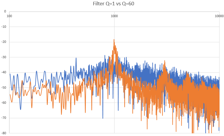
                  [EDIT] I got it added into the repo. Here's the image for faster access:

                  From this you can see signal peaks are >30 dB higher than the noise floor, and then the noise peak pushed up into the > 4 kHz band. If your voice coils are responsive enough around 4 kHz to make a vibration that can be felt you may need to suppress this with an RC filter at the Bela output, or push this peak higher (higher cut-off in the LPF) to take advantage of the speakers natural filtering...but then the noise floor in the low frequency range will come up.

                  Chosto Just a few questions :

                  What is the relation between lfo and pure_sine ? I am confused since in set_sine_oscillator_frequency, I can see the 2pif (angular frequency), but multiplied by Ts. Initially, f is 150Hz and Ts is 1/44.1kHz for pure_sine, but then f becomes sine_oscillator_tick(lfo)in set_sine_oscillator_frequency(pure_sine, sine_oscillator_tick(lfo));.

                  This part of the code is just a police siren sound. The LFO changes the frequency of the audio-frequency "pure sine" chirping up and down over the course of a few seconds. This is not part of the PDM implementation -- it's just a test signal to hear the effect in my speakers.

                  Also, I can see noise shaping, but just to be sure : if( (input - lpf1->y1) > 0.0) is the place where the feedback loop takes place, right ?

                  Yes, this is where the feedback loop takes place. The noise pre-added to the input is high-pass filtered so it has the highest noise density in the high frequency range. This noise is what de-correlates the output rate. As addressed earlier, this is dithering.

                  input = x + hf_noise_gen(hpf1, hpf2);

                  Then looking at hf_noise_gen() you see it has a 4rth order IIR high-pass applied (two cascaded 2nd order filters):

                   // Noise shaped for highest density at high frequencies
                  return run_filter(run_filter( ((float) (rand()%65536))/65536.0, hpf1)/50.0, hpf2);

                  Also, is it an IIR filter because y1 is function of y1 ? Also, your always run the biquad filter twice, does this mean that the result corresponds to a higher order filter ?

                  Yes it is an IIR filter and you are correct it is a higher order filter because the function is run twice, but notice it is run on a second set of state variables (. It is a 2nd-order filter run on another 2nd-order filter for a total of 4-order filter.

                  Notice that if you simply ran the same filter twice this would not be the same thing.

                  Chosto ryjobil by setting filtering cut-off as a non-power-of-two ratio of the bit rate

                  Saved this for last. The filter cut-off corresponds roughly to the moving-averaging interval. So if you have a bit-rate of 44.1 kHz and use a moving-average with cut-off filter at (for example) 1 kHz, then the averaging interval becomes 1ms.

                  The number of samples averaged is 44.1 kHz * (1/1kHz) = 44.1 samples. log_2(44.1) = 5.46 Bits

                  Above is a simplification to communicate the idea. Remember this is an analog filter in the outside continuous-time world, so the filter will be a weighted moving average that will be the most strongly influenced by what happened in the past 1 ms, but stuff that happened beyond 1 ms will also be averaged into the output in progressively lower amounts. An integral of the impulse response would need to be computed in order to come up with an actual equivalent resolution.

                  In either case it is more apparent quantization error is better treated as high frequency noise that you can filter since fractional bits resolution aren't intuitive units of measure. The quantization error can be treated as a signal-noise ratio more intuitively than a fractional number of bits resolution. The lower the cut-off and the steeper the filter, the lower the noise.

                  Based on the premise that audio CODECS can produce 16-bit resolution @ 44.1 kHz from a 20-MHz bit rate I would surmise a 44.1 kHz bit rate could produce 16-bit signals <50 Hz with the correct PDM algorithm and analog filtering. That said you could use the digital outputs to drive a subwoofer with fairly good fidelity (but not using my noisy dithered approach -- the modulator would need to be a proper sigma-delta).

                    5 days later

                    ryjobil Yes, you feel this correctly. In a true sigma-delta modulator the LPF is an integrator, which has extremely high gain at low frequencies. The average of the output pulse train will strongly suppress the error between the input and output at lower frequencies, so the noise tends to be the highest above the frequency where the integrator slope crosses 0dB.

                    Oh, so the quantization error is left in high frequencies, as the feedback loop will adjust the PDM signal comparing to this "low frequency average". I guess that we want to set the digital LPF to have the same "cut-off" that my class D amp / speaker so that the average is as correct as possible for the target bandwidth ?

                    ryjobil or push this peak higher (higher cut-off in the LPF) to take advantage of the speakers natural filtering...but then the noise floor in the low frequency range will come up.

                    So in addition to what I asked right above, the higher the cutoff, the higher the noiser power will be pushed toward high frequencies, as higher frequencies are taken into account for the average computation.

                    ryjobil An integral of the impulse response would need to be computed in order to come up with an actual equivalent resolution.

                    How is an integral for a given interval different from a non-weighted moving average function ? I have the intuition that they are kind of similar, even if I cannot do the math.

                    ryjobil This is correct. To my ears all of the noise sounds like white noise when I listen to my demo code through speakers.

                    So you mean that there is no particular frequency due to PWM/PDM left, right ?

                    ryjobil In a faster bit-rate system I probably would not have used this, but I think the use of dithering will be advantageous for your application.

                    May you explain why the bit rate is relevant ? Maybe because if the bit rate was really fast, the noise resulting from quantization error would have been automagically pushed toward high frequencies ?

                    Thanks,
                    Quentin

                      Chosto I guess that we want to set the digital LPF to have the same "cut-off" that my class D amp / speaker so that the average is as correct as possible for the target bandwidth ?

                      You have the right idea but one other thing you have working for you is the human body perception. Even if the voice coil responds to high frequency noise it doesn't mean the body perceives it. In the end you just need to experiment to see what is perceptible. For example, you can send out sine waves from one of the analog outputs and increase the frequency until you can no longer feel it coming from the voice coil.

                      Where I work we do vibration testing on our products using a very large vibration table driven by the equivalent of a voice coil the size of a washing machine. When a product is tested on this table at 1 kHz I can barely sense the vibration even though the sensor output indicates the same G-force as at lower frequencies, so I would guess the perception really rolls off after 1 kHz. To be fair, the total displacement at 1 kHz is less for the same G-force since the acceleration would be higher if it was controlled for the same amount of displacement. Somewhere between 100 Hz to 500 Hz the vibration on the table is fairly acute. The strength of the vibration feels roughly the same from 50 Hz to 500 Hz.

                      The bandwidth of the speaker is most likely workable for finding an optimization with a 44.1 kHz bit rate. The Class D amp bandwidth is probably too high to be much help so for your purposes it's just a power amp for the digital pulses.

                      My intuition is you will be able to generate some kind of digital pulse/noise signal that creates the desired mechanical effect without needing to add hardware filters.

                      Chosto So in addition to what I asked right above, the higher the cutoff, the higher the noiser power will be pushed toward high frequencies, as higher frequencies are taken into account for the average computation.

                      The higher the cut-off, the frequency of the noise peak goes higher, but the power in the low frequency band increases.

                      With a lower cut-off you will have less lower frequency noise/ higher accuracy, but then the higher power high frequency noise will peak at a lower frequency. The trade-off is where you want to put the noise.

                      With the dithered PDM I have proposed it will be uncorrelated in either case so you just need to see whether one optimization or the other makes any perceptible difference in your application. You can always compare it against the perceived effect from the intended input signal sent from one of the analog outputs.

                      With Bela you have the test equipment built into the platform.

                      Chosto How is an integral for a given interval different from a non-weighted moving average function ? I have the intuition that they are kind of similar, even if I cannot do the math.

                      They are similar and that is why I used the non-weighted moving average to illustrate the point. The non-weighted moving average can be integrated geometrically (it's a rectangle with area width*length).

                      Using the integral you find the area under the curve of a weighted moving average filter, so using this math would allow you to express it in terms of an equivalent rectangle that could be compared to the rectangular impulse (non-weighted moving average) filter. I don't see much value in trying to come up with equivalent N bits resolution when you can look at the filter frequency response and evaluate signal/noise ratio according to noise power rejected by the filter. The non-weighted moving average function is also a filter response that can be evaluated in the same way in the frequency domain.

                      Chosto So you mean that there is no particular frequency due to PWM/PDM left, right ?

                      This is correct. The quantization noise does not correlate to any "sample rate". The only correlated frequencies will be:
                      1) Bit rate (44.1 kHz)
                      2) Signal frequencies (which is what you want)

                      The rest is like the static you hear when trying to tune to a weak AM radio station.

                      Chosto May you explain why the bit rate is relevant ? Maybe because if the bit rate was really fast, the noise resulting from quantization error would have been automagically pushed toward high frequencies ?

                      I was evaluating this by generating the output digital pulses into a buffer and then performed an FFT on that buffer. Without dithering there were several narrow-band peaks in the spectrum that looked like tines on a comb.

                      When I added dithering it did (as one would expect) widened all of that concentrated power down into a much lower and flatter noise floor. As you can see in my above plot of the FFT of this spectrum the noise floor is relatively flat until somewhere near 4 kHz (where the LPF was set in that experiment) and then the noise peaks around 10 kHz. Even so, the noise distribution does not have any high, narrow peaks that are not harmonics of the input signal.

                        4 days later

                        ryjobil Using the integral you find the area under the curve of a weighted moving average filter, so using this math would allow you to express it in terms of an equivalent rectangle that could be compared to the rectangular impulse (non-weighted moving average) filter. I don't see much value in trying to come up with equivalent N bits resolution when you can look at the filter frequency response and evaluate signal/noise ratio according to noise power rejected by the filter. The non-weighted moving average function is also a filter response that can be evaluated in the same way in the frequency domain.

                        I have not exactly understood that part.

                        Anyway, I think that I have understood most of our conversation, and as a beginner I learned a lot.
                        Many, many thanks, I'll keep you in touch with my tests. The Bela order has been dispatched so I should receive it soon. If you go near Paris one day, don't hesitate to ping me and I'll be happy to thank you with a drink.

                          Chosto I have not exactly understood that part.

                          It is questionable whether I fully understand it myself 😉 In case you ever get a strong desire to understand it more, it's based on the principle of a filter's impulse response and convolution. That would be the first topic to start reading.

                          Chosto I'll be happy to thank you with a drink.

                          A good reason to make friends around the world 🙂