• Hardware
  • Audio Input Maximum Voltage and Input Buffer

William I just switched over to 3.3V and it runs nicely and with very low noise level. (At least in relation to what I got with the 5V from my external power supply or the Bela) The 3.3V is lower then what is noted as the recommended supply voltage for the TLC2262 I use but as far as I understand, it's capable of going down to ~2V

I suggested you'd switch to 3.3V (or the other option) as the source for your voltage reference. The opamp can still be powered from 5V: normally opamps are good at rejecting noise in the power supply (often > 80dB attenuation, see PSRR in the datasheet), so there is no need foor their power rails to be extremely quiet

    giuliomoro

    Hey,
    merry XMas and all. 🙂
    I just got the Bela Mini i want to use for the project. Lovely little thing.
    I thought about something.
    Since I‘ll need to add some kind of power input anyway, I thought about using a 9V power supply which could power the I/O opamps (and maybe Analog ins, reduced to 0..4V). I would then use a 7805 to get a 5V for the Bela. Datasheet says that it manages 1.5A, would that be enough to drive the Mini? 9V supply’s for Audio stuff are much more common then 5V, I expect that most of those are just for charging stuff and come with a bunch of noise.

    A bit more complexity but I thing it has some advantages. And I’ll have to make sure not to toast the Bela with 9V. 🙂

      William I would then use a 7805 to get a 5V for the Bela. Datasheet says that it manages 1.5A, would that be enough to drive the Mini?

      The Mini will absorb about 420mA. The 7805 will be able to handle that, but make sure you put an adequate heatsink on it, as you will be dissipating about (9V-5) * 0.42A = 1.68W on it. Also, you will need your power supply to provide enough current.

      Ok, will do. And I’ll probably update my schematic and post an updated version when I’m back on it. 🙂

      Talking about heat. Do i have to worry about the temp the A8? I want to put the whole thing in a Aluminium case. I’ll probably just heatsink the 7805 against the case but I can’t do the same with the A8...

      First of all, what you are doing for the preamp will work lest it sounds like I'm saying otherwise. If it sounds good to your ears, go with it. The rest of this gives you more ideas if you get dissatisfied with the result.

      William @ryjobil About the diodes. I wanted to add the gain control to fully use the 16bit. Otherwise a dry signal from a single coil guitar probably wouldn't use much of the 16bit.

      I fully understand and agree with the intent. The salient characteristics of the strategy I expressed uses harder clipping to reduce the range over which the nonlinear function is operating. The point is to create a wider region of operation where the clipping mechanism has almost zero effect until the output signal gets more near to the rails. That way clean is pristine, but occasional clipping isn't ugly.

      The way you have it implemented the circuit will be distorting even when you want it clean if you're using the full 16-bit resolution. I did some simulations on your circuit where the clipper was a Schottky diode in series with an Si diode, for 1.7Vpk-pk clipping. At 0.8Vpp there is about 1% distortion. Full range (1.8Vpp) the distortion increases to about 20%. Basically you would have 15 bits of clean dynamic range and you lose the MSB to increasing diode nonlinearity.

      A traditional back-back diode clipper is actively affecting the sound long before you get audible buzz. Maybe you always play with a little dirt and don't mind this. On the other hand, 15 bits is pretty good so maybe this will be ok if you use 2 series diodes.

      Here are a couple ideas for how I am working around this problem. Maybe this will make it more clear what I'm saying and perhaps spark some ideas.

      Discrete implementation using "diode compression op amp" (5V "Vcc" needs to be filtered with R and large C since this doesn't have much PSRR to speak of)

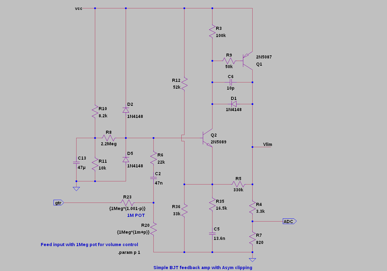
      Op amp-based implementation. The key point is clean headroom before diodes can become forward-biased, and then output resistor divider brings the max clipped signal level down to within the ADC input range. You can put as much gain on the input side of things to make up for it.

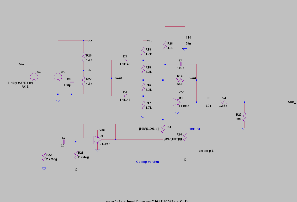
      The following simulation plots are from the discrete version, but the op amp version is designed for the same frequency response while the op amp clipping is symmetric:

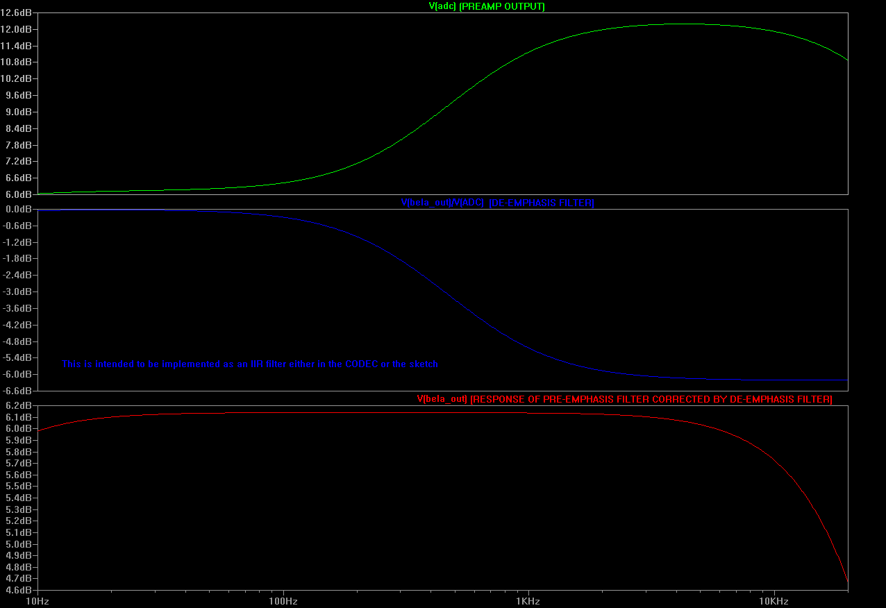
      And a transient sim to see the soft clipping as well as the amount of gain available on the first stage.
      I noticed I made a mistake (notice 870mVpk-pk). Change R4 to 2.2k and R7 to 1.8k to get 1.9V peak-peak assuming Vcc = 5.0V. One could also use a 20k resistor parallel to 5k pot. Adjust the setting on the 5k pot to get full-range input when the circuit is slammed rail-rail. The value of 4k in that lower leg is important to the output symmetry (hint you can tweak clipping symmetry by changing this resistor value).

      FWIW I'm using 12V supply and a 600 kHz switcher to get the 5V. This switcher I designed myself, but you can get SMPS DC-DC converters from DigiKey or other distributor of choice. Murata has a good number of these.

      This might be a helpful tip if you have a hard time managing the heat from a 7805.

      Hey,

      thanks for your input! I'll really have to see how much room i have for the pre/post amp circuit. I'll be working with through hole components and a perfboard. So stuff tends to take quite a bit of space.
      Regarding the voltage supply, I already found a switching regulator that works with 400-500kHz as an alternative to the 7805.

        William I'll really have to see how much room i have for the pre/post amp circuit.

        Yes, there is another consideration. As for me, I use little SOT package dual PNP-NPN complementary pair package and SMT capacitors, so either of my circuits could be made to fit on a board the size of a thumbnail.

        The circuit you posted has simplicity, making it easy to construct in a small space, even with large TH components. The ears give the final opinion that counts.

        Good on the switching regulator. You can always filter the output if you get noise from it, but you can't fix heat with a filter 🙂 . An extra R&C is small compared to a large heat sink.

        Have fun

        @giuliomoro
        Hey, I have a quick question regarding powering the bela mini. Since I want to put the whole thing in an enclosing, I want to use Pin P1-1 for powering the mini with 5V from a 5V/1A switching regulator. However, for programming the thing, I probably want to temporarily connect a USB mini plug as well. Do I have to worry about the two getting in each others way? Or does the bela notice that it doesn't need to draw power from the USB pin?

        Otherwise, I could add a small DIP switch to temporarily turn of the "internal" 5V supply but I've noticed that those switches don't really want to manage up to 1A. (Even though the Bela probably will only have to deal with ~600mA max)

        Another short question: What are the connectors used for the Audio I/O on both Bela and the Mini? I'm looking for a way to connect the board to I/O jacks and so on with 2.54mm pitch connectors. Found JSTs as an alternative but I'm still curious what is used on the Bela,

          William However, for programming the thing, I probably want to temporarily connect a USB mini plug as well. Do I have to worry about the two getting in each others way? Or does the bela notice that it doesn't need to draw power from the USB pin?

          According to this, that pin (P1.01)is the equivalent of what is P9.05/P9.06 on the BeagleBone, which is the one where the external power from the barrel jack goes. This means it's actually meant to be used at the same time as the USB power: the power-management IC should be able to switch seamlessly from USB to the 5V IN.

          William (Even though the Bela probably will only have to deal with ~600mA max)

          I didn't measure the inrush current, but once it's up and running it's between 400mA and 420mA. I didn't manage to see any variation depending on CPU usage.

          William Another short question: What are the connectors used for the Audio I/O on both Bela and the Mini? I'm looking for a way to connect the board to I/O jacks and so on with 2.54mm pitch connectors. Found JSTs as an alternative but I'm still curious what is used on the Bela,

          Hopefully this should help.

            William However, for programming the thing, I probably want to temporarily connect a USB mini plug as well.

            It would be a good idea to have a blocking diode on your external 5V supply unless you know for a fact that your regulator already has this function. Otherwise if your regulator output is less than USB power it might function as an extra load on the 5V rail.

            Schottky or STMicro FERD are good choices for low forward drop.

            Most switching power supplies won't sink current, so by rolling a dice you would probably find 5/6 don't need anything extra.

            I would add something extra in case you have one of those synchronous topologies that will sink and source.

            The switching supply I picked out doesn't come with protection, datasheet isn't very specific but it mentions that one should use a blocking diode. Does it make sense to use a FQP47P06 PMOS in parallel with the diode to block the supply? (gate to ground, drain to supply and source to Bela P1)

            With a 1N5817 Schottky, I get a 200mV voltage drop across the diode at 500mA. Adding the PMOS reduces the voltage drop to <30mV, the PMOS has quite a low drain-source resistance of 0.027 Ohm. I use the same setup to protect my circuit against reverse polarity power supply and it seems to be the same kind of situation, right?

              William Does it make sense to use a FQP47P06 PMOS

              Not without accurate circuitry to precisely control it. The problem with the configuration you suggest is that this doesn't detect reverse current flow. It is only reverse connection protection, so it won't protect against the case when USB power is 5.1V and power supply power is 5V, where you could sink enough current at a small reverse voltage drop to activate USB overcurrent protection. Depending on the hardware configuration in the host computer sometimes this shuts down all of USB, and in some cases (curse Windows) requires a reboot or wading deep into system control stuff to reset the USB controller and get USB devices to work again.

              I wouldn't think 200mV drop as being a real big deal, but if you really want to go for the high precision stuff, look at one of these with an N FET:
              https://www.analog.com/media/en/technical-documentation/data-sheets/4358fa.pdf

              It works by modulating the FET at a 30mV forward drop. When the bus supply gets nearly equal to the upstream supply voltage it shuts off and lets whatever is feeding the bus take the load. This shut-off occurs in less than 500ns.

              Other vendors make similar devices, but the LT/analog is the most sure-fire for preventing backflow current when sharing a bus, but I think TI has some eFuse products with the integrated FET that do pretty well -- you just have to look closely at these because some use a negative threshold for preventing backflow current and they can sometimes sink as much as several amps before they detect it and shut down the device.

              I didn't really look into how the boards are designed, but the Power Management IC that they have does have separate inputs for 5V coming from USB and from an external AC/DC converter, so I would guess that they have wired them appropriately and that the "AC" input will be isolated from the "USB" one. At least, this is what would appear from the diagram on page 1 of the datasheet. The functional block diagram (section 8.2) is a bit more confusing in that it claims that both "AC" and "USB" come "from USB connector", but I am almost sure that is an error in the datasheet, as that is in disagreement with the description of the pin in the table "Pin Functions" in section 6, which states

              AC        AC-adapter input to power path. Connect this pin to an external dc supply

              @giuliomoro , @William

              I looked at this datasheet. Figure 11 on Page 27 gives a good functional block diagram.

              This is exactly the function you need. It is able to detect AC and USB input power sources and smartly select which one it will use, routing through low RdsON FETs. So the question is where are these pins connected on the BBB?

              I checked that schematic and looks like the input jack goes to the AC input pin on that PMIC, so as long as you are connecting your external AC adapter to a pin that connects directly to the power input jack you don't need to add anything extra to the circuitry.

              giuliomoro According to this, that pin is the equivalent of what is P9.05/P9.06 on the BeagleBone, which is the one where the external power from the barrel jack goes. This means it's actually meant to be used at the same time as the USB power: the power-management IC should be able to switch seamlessly from USB to the 5V IN.

              There you are

              15 days later

              Hey!

              I've prototyped the whole thing on a breadboard, now that I have most of the components together. I immediately run into an issue. With my circuit from above, I use a now 10k/10k voltage divide with a buffer to create my half-voltage reverence source. However, driving the Bela from the same power supply via a switching regulator adds a bunch of digital noise to my 9V,my 5V and somehow also bleeds in to GND. Which is really odd.

              The digital noise mostly bleeds into the audio signal from the voltage reference. I changed the circuit to include a big 6.8u capacitor between V+ and GND which helps but doesn't reduce the noise sufficiently.

              Do you have any tips regarding keeping the voltage supply clean of noise? I added 1u or 6.8u cap's to the voltage supply but that didn't seem to help. I might have to add a bigger cap but I don't have any bigger values here...

                William
                As long as your ground reference is coming from the same ground reference as the CODEC then ground noise won't be the issue. Use the ground at the header for audio I/O and that will at least eliminate that as a source of problems.

                Use as large of resistor from +5V in series to your op amp Vcc as you can use -- the size will be limited by the current draw from your circuit and how much voltage drop you can tolerate.

                Then put in 100uF cap and parallel some smaller (like 47 nF) ceramics to reject high frequency noise.

                Add a large filter cap from your 2.5V ref to ground.

                Again, all ground references right off the audio ground. To reject noise from a power supply you either need really large caps (like several low ESR 470uF in parallel) or put in a series impedance to work against. Cut-off frequency of your filter is 1/(2piR*C). If you don't purposely add an R there, then the equivalent "R" coming out of the power supply is very very small and you need huge and really low ESR caps to make a difference.

                William I've prototyped the whole thing on a breadboard,

                This is your other problem. When you get the thing nicely layed-out and connected with short leads things will clean up a bit. Breadboards are big antennas for anything with fast edges. You can help a bit if you are using a breadboard on a metal plane that is grounded. Some BB's come that way, others you can just set on a metal box and ground the box.

                Anyway between the combination of those ideas you can get it cleaned up some more.

                So add a RC lowpass filter to the voltage supply of the OpAmps? I'll check again tomorrow, done for today. I noticed that the biggest source of the noise still was the reference voltage OpAmp. I added a RC filter with 10kOhm and 100uF cap at the output of the OpAmp, that helped a lot to get a clean reference voltage. (Also, I'm working with 9V for the Pre/Post circuit and derive the 5V with the switching regulator. So my reference is at ~4.5V)

                When I work with the low voltage guitar signals, I still have SNR issues with the digtial noise. I assume that my OpAmps (currently OPA2134) do a sufficient job at noise rejection but I'll try the filter trick anyway tomorrow.

                The purpose of adding the RC to the op amps is to bypass high frequency noise right where it comes in. It also serves as a double filter on your Vref. It's just 2 stages of filtering in the end.

                An interesting thing to consider is PSRR of the op amp vs frequency.
                http://www.ti.com/lit/ds/symlink/opa2134.pdf
                Look at Figure 11.

                If some of the audible noise is a result of quasi-periodic pulses with fast edge rates then it may be this energy is going right through the op amp. If the pulse widths or fundamental switching frequency changes at audio frequencies then 10MHz oscillations on each switching edge can become a source of energy that accumulates as audible noise.

                I would say it is possible for switching power supply noise to feed through and turn into something audible even though I agree this is less likely and it is probably not most of the noise. If it is a significant part of the noise, this is where something like 47nF ceramics can really do a good thing because they will bypass fast edge rates of SMPS switching pulses.

                If this is still on your breadboard, then I think you will see some improvement when you move it to a more compact and well layed-out implementation.

                To improve rejection on the Vref input, you can use a 5V->100ohm->4.7V Zener, then divide your 2.5V ref off the 4.7V zener and also use capacitors for further filtering. The Zener shunt will give you a good bit of noise rejection right at the start. A linear regulator IC could do something similar for cleaning up Vref.