Bela mini w/ multichannel expander
Puredata

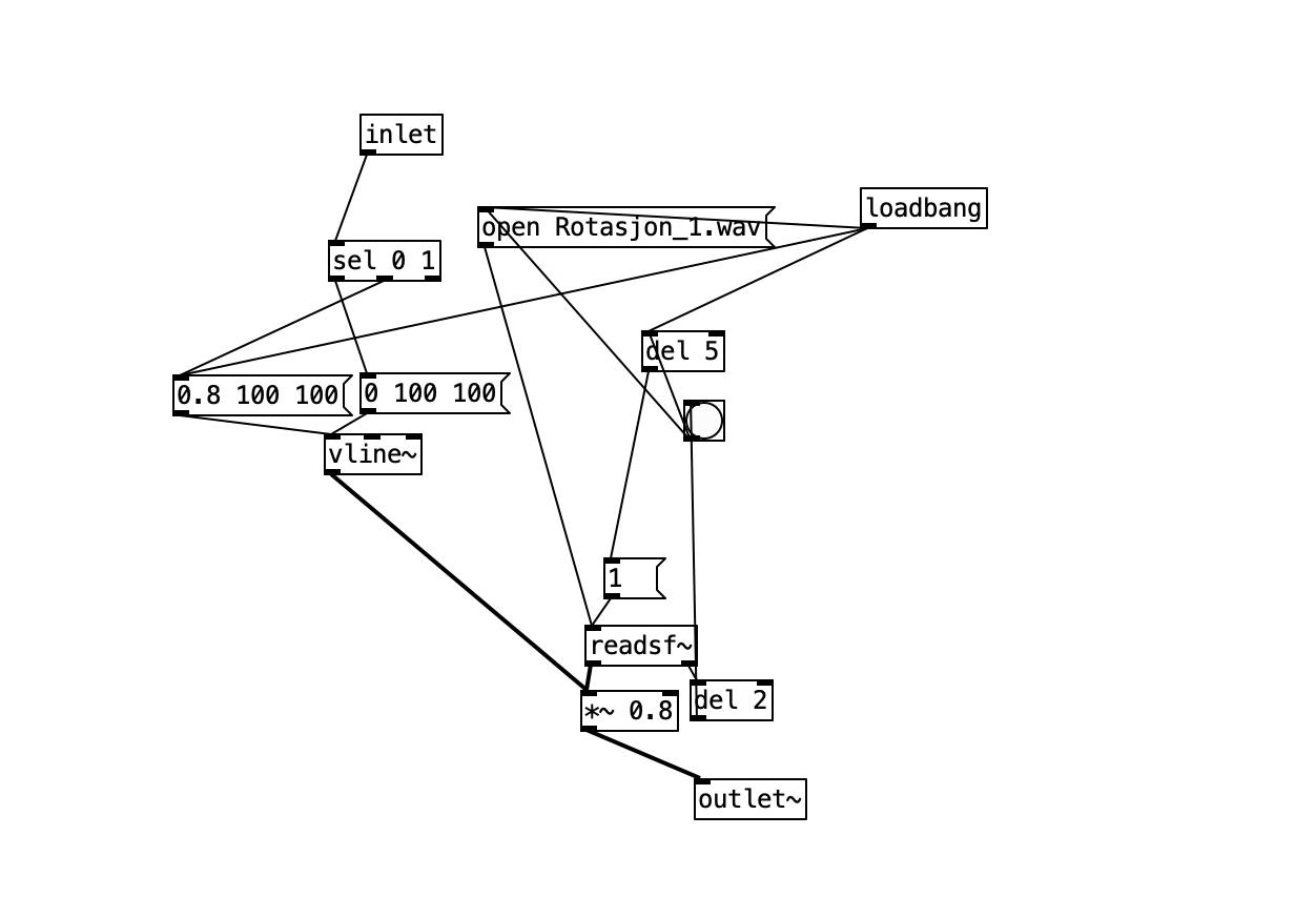
The only thing my patch needs to do is to read 1 when the digital pin receives power and 0 when it does not. As I understand, these are the default values received in pd from Bela with the digital pins. However, I receive nothing.

The digital pin receives between 2.5 - 3.3v when the sensor is engaged and is supposed to receive 0 when it is not. I have measured with my multimeter that there is actually power supplied. As my multimeter has never measured exactly 0 I have tried putting a resistor on the ground wire going between the shared ground wire and the gnd pin on the Bela.
Still, I am receiving nothing. What could I have missed here? Is the problem that I can't get an absolute 0? Have I executed the pull-down resistance wrong? Is the problem something entirely else? I can't figure this out and I'm promply approaching deadline. Any help would be greatly appreciated!

Pictured is my Bela with connections and the programmed power supply. Also a test patch that should be able to print 0 and 1 from the different channels.


6 days later

giuliomoro So I've been trying to strip the challenge down even further to make it easier both for myself and you guys to understand.

I am now supplying 3.3v from the bela and returning to gnd on the same bela. I have copied the pull-down resistor schematic exactly on a breadboard, EXCEPT I'm not using a button. Rather, I'm using an LED to make sure there is power. Instead of a button, I'm manually connecting and disconnecting the power supply. Is there any reason this would not work? What functionality would the button add to this? This is in essence the same way the finished project will work, except the power supply is external.

Some background on the project:
I am using the Bela Mini wth the multichannel extender. The project is a tunnel with 5 laser sensors. Each sensor has a correlating power supply feeding 3.3v when triggered by the sensor. In turn, it feeds 0v when not triggered. I will use this to trigger on and off 5 separate sounds going to 5 separate speakers, all acting independently of each other. The 5 power supplies are connected to 5 different digital pins and the ground cables are soldered together into one common gnd pin on the bela.

In my mind, this should be quite straightforward, but I'm not receiving any signals into the bela.

Photos of my puredata prototype and breadboard setup. The breadboard photo does not show a resistor going to ground. I've tried both with and without the resistor (10k). Photo of the signal generator in the previous post. This is a photo of the breadboard and Bela set up for a simple digital in test.
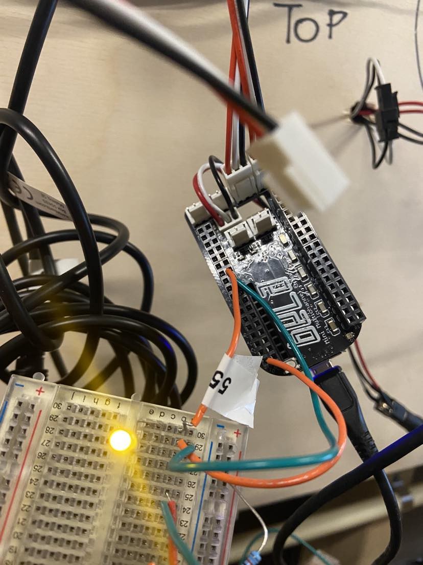
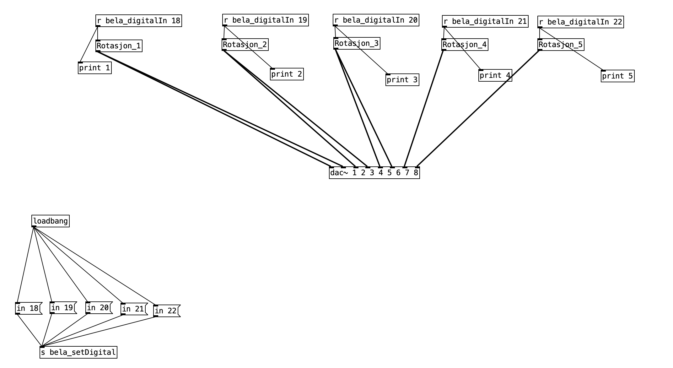
The name of the receiver should have no space between In and the number, e.g.: [r bela_digitalIn18] . I missed that the previous time.

Is the LED connected directly between 3v3 and GND? I would expect it to quickly blow in that case! I don't see how the resistor is used in your circuit.

Forget about the LED and connect your digital pin D1 directly to 3v3. You should get a print "1: 1".

    giuliomoro Oh, no space... I can't believe I missed that. Unluckily I managed to fry my board today while reversing the polarity, so I won't be able to try it for a while... Thanks a lot for your patience with this noob 🙂

    Update: The space issue solved it. No step-down necessary. Can't believe I missed it. Thank you!