kieran the sensor is hooked up to analog pins 4 and 5.
Nomenclature of Arduino pins is sometimes confusing. Pins may be labelled as "analog" but actually used for some digital signal in a specific application. In our case we are using the I2C bus's SCL and SDA lines, so on your board you'll need to find what pins these signals are available on.
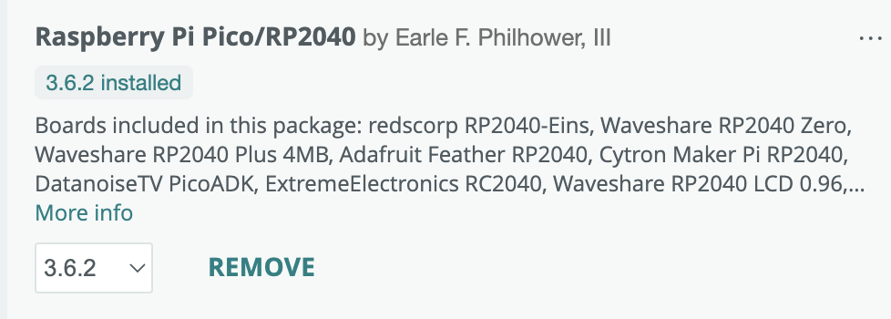
Is this the board you are using?

From what I can see there, you can access the I2C1 and I2C0 SDA and SCL signals on several pins. As the Trill library uses the Wire.h under the hood, you'll have to refer to that to see what pins are used by default and whether that can be changed. This page claims that pins can be changed but it doesn't say which ones are the default ones. We are using Wire.h (and not Wire1.h), so that should mean we are using the I2C0 bus. Besides that, the documentation doesn't state the meaning of the pin number argument to the setSDA() and setSCL() calls ... and this other page doesn't make things much clearer, except one can infer that it's the number of the GPx pin. So for instance to use I2C0_SDA on pin 1 (GP0) and I2C1_SCL on pin 2 ( GP1), you probably need to call within your setup() function:
setSDA(0);
setSCL(1);
before you call .begin() on the Trill object.
Or it could be that you should call
Wire.setSDA(0);
Wire.setSCL(1);
instead ... or yet something else.
I don't have a Raspbery Pi Pico, but on the Arduino 2 IDE I followed the instructions here to install the board files that the above "documentation" refers to and it would seem that the second one works (i.e.: it builds without errors).
E.g.:
#include <Trill.h>
#include <Wire.h>
Trill trill;
void setup() {
// put your setup code here, to run once:
Wire.setSDA(0);
Wire.setSCL(1);
trill.begin(Trill::TRILL_BAR);
...
}